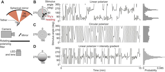
Fig. 3.
A flight simulator for studying polarized light navigation in tethered, head-fixed flies. (A) Schematic diagram of the apparatus (after Warren et al., 2018). The difference in wing stroke amplitude was coupled to the angular velocity of a polarized light stimulus, permitting head-fixed flies to steer. Stroke amplitude was monitored via an infrared camera. Linearly polarized light was generated by a rotating polarizer beneath the fly and then reflected onto the eyes via an overhead spherical mirror. (B) Example of an individual's flight orientation relative to the polarization axis. Left: polarizer orientation over the 15 min flight; 0 and 180 deg reflect headings where the axis of polarization is aligned with the longitudinal body axis. Right: distribution of headings during flight. The distinct peaks at 50 and 230 deg reflect axial symmetry of the stimulus. (C) Example control data with circular polarizer. (D) Example data with combined intensity cue and linear polarizer. Here, 0 deg is heading with the bright portion of the stimulus in front of the fly. In this example, the fly stabilizes the stimulus at a single heading of 168 deg. Adapted from Warren et al. (2018).

