
FIGURE 1.
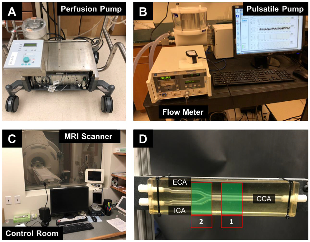
(A) Perfusion pump for continuous flow experiments. (B) Pulsatile pump, including the conditioning head on the top left. (C) Control room for the 4D Flow MRI experiments. The room where the scanner is located can be seen through the window. Long tubing was directed through the dividing wall, connecting the pump to the silicone model on the MRI scanner. (D) Silicone in vitro model of the carotid artery bifurcation. Data were acquired at the [1] CCA and [2] bifurcation for comparison between velocity measurement techniques.