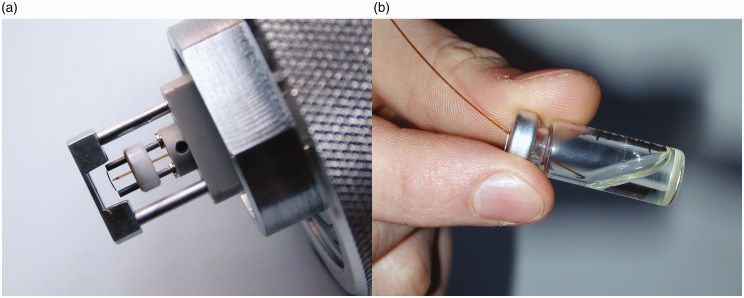
Figure 15.
LIFDI probe setup and operation. (a) The LIFDI emitter has a feedthrough for the sample transfer capillary to be pushed close from the backside. The setup shown here also carries the counter electrode at the tip of the probe. (b) Supply of sample to the emitter by dipping the atmospheric end of the transfer capillary into the sample solution stored in a capped septum vial. Adapted from Ref. [56] with kind permission. © SAGE Publishing, 2004.

