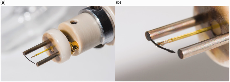
Figure 17.
(a) Emitter for LIFDI with a central hole in the ceramics part to feed through the transfer capillary. The capillary needs to be adjusted with respect to the emitter as to enable smooth transfer of sample solution onto the emitter. (b) Wetting of the emitter with sample solution with the tapered tip adjusted close to the emitter surface but still just not touching it. The liquid is spreading along the activated zone. In normal LIFDI operation, this step would be performed inside the ion source.

