
Fig. 5.
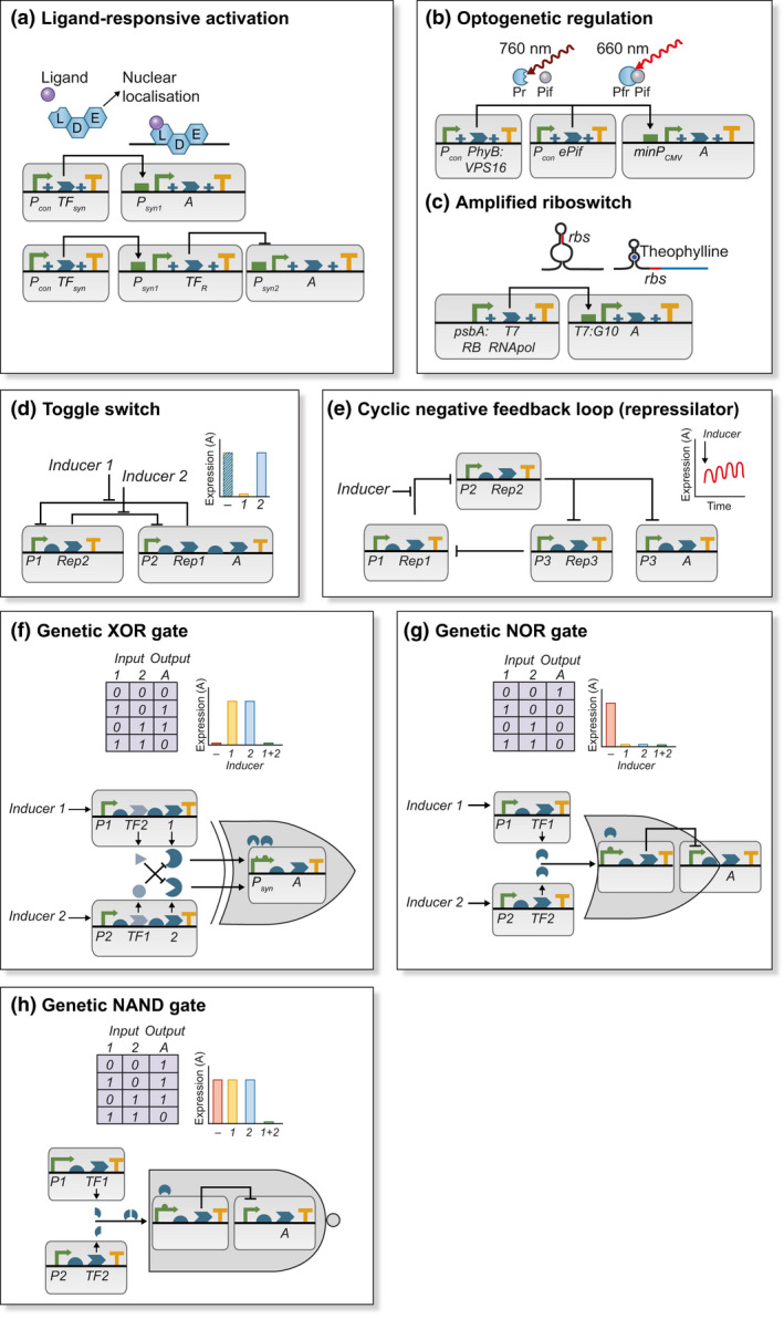
Synthetic genetic switches and circuits for regulating gene expression. (a) In simple ligand‐responsive switch, synthetic transcription factors (TFsyn) formed from ligand‐binding (L), DNA‐binding (D) and effector (E) domains are expressed from a constitutive promoter (Pcon). In the presence of the ligand, TFsyn localises to the nucleus and binds to a synthetic promoter Psyn1 activating expression of target gene ‘A’. The switch can be converted to a repressor by fusing Psyn1 to a repressor of transcription (TFR) that binds to cognate motifs in Psyn2. (b) In far‐red light (760 nm) there is no expression from the minimal promoter, minPCMV. In red light (660 nm), phyB, C‐terminally fused to the VP16 transactivation domain, interacts with an engineered phytochrome interacting factor (ePIF) and binds to cognate sites in minPCMV inducing expression of ‘A’. (c) The ribosomal binding site (rbs) is located within a theophylline‐responsive riboswitch in the transcript of T7 RNA polymerase. In the presence of the ligand, translation is possible. This subsequently activates expression of target gene ‘A’ from a synthetic T7:G10 promoter. (d) In a genetic toggle switch, repressor of transcription 1 (Rep1) inhibits transcription from promoter 1 (P1) and is induced by inducer 1. Repressor of transcription 2 (Rep2) inhibits transcription from promoter 2 (P2) and is induced by inducer 2. Thus, in the presence of inducer 1, P1 is de‐repressed, resulting in repression of P2 (OFF) and, in the presence of inducer 2, P2 is de‐repressed resulting in repression of P1 (ON). In the absence of any inducer, the switch may stabilise at either setting. (e) A cyclic negative feedback loop or ‘repressilator’ can be used to produce oscillatory expression of a target gene ‘A’. The exact amplitude and period of oscillations are dependent on the repressor‐promoter affinity and stability of the repressors. (f–h) Boolean logic can be genetically encoded to enable output (expression of target gene ‘A’) to be dependent on the presence of multiple inputs (inducers). (f) In this realisation of an XOR gate, expression is induced by either transcription factor 1 (TF1) or 2 (TF2) but not both. This is achieved by co‐expression of an interacting protein for the competing TF preventing activation of Psyn. (g) In the NOR gate, either TF can activate expression of a transcriptional repressor thus repressing ‘A’. (h) In the NAND gate, repression of the transcriptional repressor requires induction of both parts of a heterodimeric TF. The behaviour of each circuit is shown as a truth table and as idealised gene expression of ‘A’.