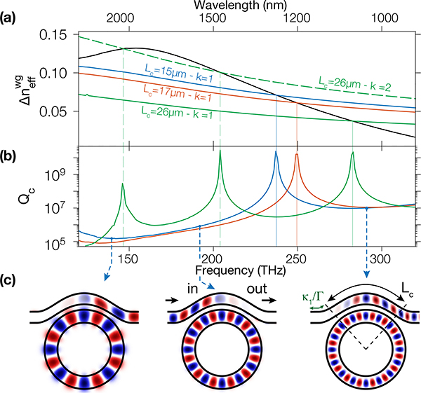
Fig. 2.
(a) Difference in effective index between the ring and waveguide mode (black) and the anti-phase matching condition (right hand side of Eq. (6)) for Lc={15, 17, 26} μm (blue, red, green). Lc=26 μm supports an anti-phase condition for both the first and second order (solid and dashed green lines). (b) Qc for the corresponding pulley lengths. (c) Cartoon depicting the behavior of the electric field for the three frequencies shown as dashed lines in (b), corresponding to the DW and pump frequencies, for Lc =15μm

