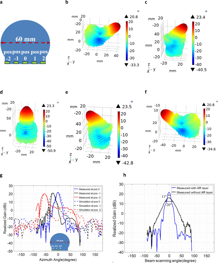
Figure 6.
Anti-Reflective layer mitigates the reflection problems present in QCTO method and improves the gain values. Simulated 3D far field radiation patterns of modified Luneburg lens antenna at 30 GHz with the presence of λ/2 (at 26 GHz) thickness anti-reflective layer. lens’s beam-steering angle at (a) − 55° (pos − 2); (b) − 22° (pos − 1); (c) 0° (pos 0); (d) 55° (pos 2); e) 22˚ (pos 1); (f) feed source locations at the planar excitation surface. (g) measured and simulated gain patterns comparison at 30 GHz with and without the presence of AR layer at 3 excitation locations (pos − 2, pos − 1, pos 0).

