

Abstract
Injection molding of plastic optical lenses prevails over many other techniques in both efficiency and cost, however polymer shrinkage during cooling, high level of uneven residual stresses and refractive index variations have limited its potential use for high precision lenses fabrication. In this research, we adopted a newly-developed strong graphene network to both plain and convex fused silica mold surfaces and proposed a novel injection molding of plano-concave lenses with graphene coated fused silica molds. The unique combination of the graphene coating and fused silica substrate maximize the mechanical properties of the mold and coating materials, namely high hardness, low surface friction, and high heat preservation effect during cooling since fused silica has low thermal conductivity. This advanced injection molding process was implemented in molding of plano-concave lenses resulting in reduced polymer shrinkage. In addition, internal residual stresses, and refractive index variations were also analyzed and discussed in detail. Meanwhile, as a comparison of conventional injection mold material, aluminum mold inserts with the same shape and size were also diamond machined and then employed to mold the same plano-concave lenses. Finally, a simulation model using Moldex3D was utilized to interpret stress distributions of both graphene and aluminum molds and then validated by experiments. The comparison between graphene and aluminum molds reveals that the novel injection molding with carbide-bonded graphene coated fused silica mold inserts is capable of molding high quality optical lenses with much less shrinkage and residual stresses, but more uniform refractive index distribution.
Keywords: Injection molding, graphene coated fused silica mold, shrinkage, residual stresses, refractive index variation
1. Introduction
Injection molding of optical grade plastic lenses has been a competitive technique that enables production efficiency improvement and cost reduction of optical fabrication because its volume manufacturing capability [1]. However, properties of the molded polymer optics can be significantly altered as it experiences large thermal changes, mainly during cooling phase, which often results in injection molded optical components with several major issues. One of them, i.e., residual stresses can be formed due to polymer’s differential shrinkage during cooling, and this in turn will result in warpage of the molded part and may even induce stress-cracking under extreme conditions. Moreover, the surface profile of an ideal optical lens must be precisely controlled according to optical design to fulfill its design functionality. However, molding material shrinkage and internal stresses can induce material distortion, which limits the replication quality of the molded components. Previously, Matsuoka et al. [2] investigated an analysis system for injection molding to predict warpage of products with consideration of the filling-packing-cooling process of both mold and polymer. Hastenberg et al. [3] proposed a modified layer removal method to measure residual stress distributions within the injection molded flat plates. Jansen et al. [4] studied the influence of process parameters including packing pressure, injection velocity, and melt temperature on polymer shrinkage. Yang et al. [5] systematically characterized the influence of the shape and layout of micro features on replication accuracy and theorized a formation mechanism of incomplete filling defects in injection molding.
Refractive index is another important property that will change due to thermal changes in injection molding process. Previously, a number of studies have been performed to investigate the refractive index variation caused by material experiencing material softening and solidifying. For example, Haken et al. [6] and Kakiuchida et al. [7] conducted experiments to uncover the relationship between refractive index variation and different fictive temperatures in molding process. Fotheringham et al. [8] studied the refractive index variation with consideration of various cooling rates. Su et al. [9] established an FEM model to calculate refractive index variation in optical glass. Yang et al. [10] designed an optical experiment to discuss the effect of different level of packing pressures on wavefront distribution and refractive index variation and compared the measured refractive index variation with the simulated one. Li et al. [11] proposed an optical aberrations measuring method for calculating the optical distortion of progressive addition lenses in injection molding and verified by both experiments and simulations.
According to the aforementioned studies, profile change in injection molded polymer lenses induced by cooling shrinkage, plus residual stresses and refractive index variation generated in thermal treatment cannot be completely erased but can be minimized by reducing the cooling rate to a certain level. We therefore attempted to replace the conventional injection mold materials such as aluminum or stainless steel with materials with lower thermal conductivity to achieve a slower cooling phase for injection molded lenses. Fused silica is one of the available options because of its high hardness, flexible processing methods and heat preservation effect due to the fact that it has a low thermal conductivity of 1.05 W/(m2•°C) relative to the aluminum substrate (250 W/(m2•°C)). Besides, silicon materials may experience adhesions between itself and polymer, either resulted from anodic bonding or chemical bonding at molding temperature [12]. Therefore, a newly-developed graphene coating [13] which has a smooth surface with a lower friction coefficient of 0.0292 compared with the aluminum substrate (0.0763), was applied on the surface of fused silica mold to avoid possible adhesion and provide better polymer flow. The new injection molds with unique combination of graphene coating and fused silica substrate will lower the cooling rate, thereby obtaining high quality optical elements with less refractive index variation and low level of uniform stress distribution.
In this paper, we proposed a novel precision injection molding process with graphene coated fused silica mold inserts to fabricate plano-concave lens. The carbide-bonded graphene layer characterized by its hardness higher than silicon, highly smooth surface and anti-abrasion was coated on both plano and convex fused silica mold surfaces respectively. Assembled with outer molds and mounting plates, a novel injection molding setup with graphene coated fused silica mold inserts was established to fabricate plano-concave lenses. As a comparison, conventional injection mold material, aluminum molds with the same shape and dimension were also diamond turned to be tested under the same injection molding conditions with the graphene molds. The injection molding experiments were carried out and the profile accuracy, residual stress distribution and refractive index variation of injection molded lenses by both graphene coated fused silica molds and aluminum molds were evaluated. In addition, with heat conduction results between polymer and different molds calculated by basic thermodynamic equations, residual stress distribution was numerically determined by using a commercial FEM (finite element method) based software Moldex3D (www.moldex3d.com) and the results agree with the experiments well. The comparison between graphene coated fused silica molds and aluminum molds demonstrates that new injection molds developed in this study are capable of producing high quality lenses for optical fabrications.
2. Fabrication
2.1. Mold preparation for injection molding
The mold preparation process is illustrated in Fig. 1(a). To build the graphene coated fused silica mold inserts, a pair of fused silica lenses with plano and convex surfaces was employed as upper and lower substrates, respectively. For conventional graphene layers, two-dimensional atom structures prevent them from being firmly adhered to the substrate, which makes them a less preferred coating option. Lately, a durable three-dimensional so called carbide-bonded graphene coating was proposed by Huang et al [13] to enhance the bonding strength between silicon material substrate and coating. In this coating design, new graphene layers are firmly deposited on fused silica surfaces and can maintain high stability at elevated temperature. Meanwhile, two cavities that can perfectly fit both fused silica mold inserts in were diamond machined in the center of top surfaces of two cylinder holders on the 350 FG precision machine (Moore Nanotechnology Systems, Keene, New Hampshire). The two holders made of aluminum were designed to match the cavity size for the molds on two plates of the injection molding machine. Therefore, the assembled plano and convex graphene coated fused silica molds were schematically shown in Fig. 1(b). As a comparison of the new graphene coated fused silica molds, another set of plano and convex aluminum molds with the same shape and size was also machined, as shown in Fig. 1(c).
Fig. 1.
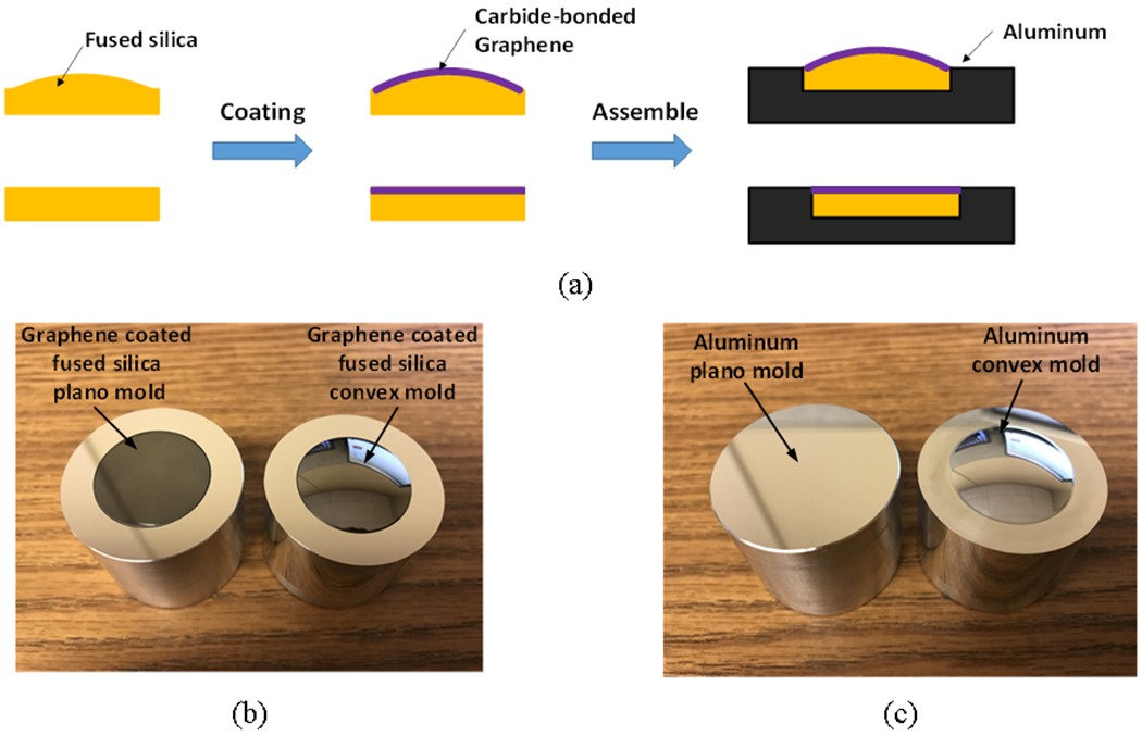
(a) Preparation of carbide-bonded graphene coated fused silica molds, (b) Graphene coated fused silica upper and lower mold inserts, (c) aluminum upper and lower mold inserts.
2.2. Injection molding of plano-concave lenses
A microinjection molding machine (LD30EH2, Sodick Plustech) was employed for plano-concave optical lenses fabrication with both graphene coated fused silica molds and aluminum molds. With a maximum capacity of 30,000 kg clamping force and 0.250 m/s injection velocity, this machine has an injection plunger for small loading size with higher accuracy than conventional injection molding machine. An optical grade PMMA was utilized for the work, and the material properties are listed at the top of the left column in Table 1.
Table 1.
Material properties and parameters of PMMA (Plexiglas RV825).
| Material properties | Values | Tait PVT model | Values |
|---|---|---|---|
| Transition temperature (°C) | 101 | b1l (cc/g) | 0.85982 |
| Density (g/cm3) | 1.172 | b1s (cc/g) | 0.860702 |
| Refractive index | 1.489 | b2l (cc/g · K) | 0.0005697 |
| Luminous transmittance | 92% | b2s (cc/g · K) | 0.0001995 |
| Water absorption (24 h immersion) | 0.3% | b3l (dyne/cm2) | 2.09×10⁹ |
| Viscosity Cross-WLF model | Values | b3l (dyne/cm2) | 2.73×10⁹ |
| n | 0.21 | b4l (1/K) | 0.0049083 |
| r* (dyne/cm2) | 1.48×10⁶ | b4l (1/K) | 0.003394 |
| B (g/cm · s) | 1×10⁻¹⁶ | b5 (K) | 383 |
| Tb (K) | 24294 | b6 (cm2 · K/dyne) | 2×10⁻⁸ |
| C | 0.0894 | ||
Before conducting injection molding, PMMA were placed in a dryer at 85 °C for 24 h to remove moisture absorbed in PMMA when stored in the open air. The entire molding experiment involves three steps: namely, filling, packing, and cooling, which schematically illustrated in Fig. 2. A pile of PMMA pellets were first heated to 250 °C, which largely exceeded the transition temperature to a temperature that will melt the polymer. A proper injection pressure and velocity were then set to ensure sufficient PMMA resin to be injected into the mold cavity and to obtain a complete filling. Once the cavity is filled, a pressure is maintained to hold the cavity and compensate for volume shrinkage of the plano-concave lens. Finally, a chiller was used to cool the molding assembly to temperature of 70 °C, ensuring that the lens solidified and could be successfully ejected. When cooling was completed, the mold was opened and a finished lens was released. Afterwards, the injection molding process with aluminum molds was performed using the same conditions and lens injection molded by aluminum molds was obtained as well. The injection molding conditions of the entire process is summarized in Table 2.
Fig. 2.

The schematic showing the process of injection molding with graphene coated fused silica molds.
Table 2.
Injection molding condition for plano-concave lenses.
| Parameters | Values | Parameters | Values |
|---|---|---|---|
| Melt temperature (°C) | 250 | Packing time (s) | 6 |
| Mold temperature (°C) | 75 | Cooling temperature (°C) | 70 |
| Injection pressure (MPa) | 100 | Cooling time (s) | 25 |
| Packing pressure (MPa) | 80 |
2.3. Wavefront measurement setup
After the PMMA lenses are molded, the wavefront variations of the lenses molded by using graphene coated fused silica molds and aluminum molds are measured using an SHS (Shack–Hartmann wavefront sensor) [14]. Fig. 3 schematically shows the SHS-based wavefront measurement system. In this optical setup, a He-Ne laser (λ = 632.8 nm) first generated a beam of parallel light with planar wavefront and it then passed through a pair of polarizers to lower its intensity to prevent saturation on the CCD image plane. Planar wavefront would be distorted when going through the specimen if refractive index variations existed in the molded lenses. Eventually, the distorted wavefront was imaged and displayed on the CCD screen. The system can measure wavefront change at the level of ±10−5 mm, which is much lower than the anticipated wavefront change (10−4~10−3). Specially for this case, the plano-concave lens has a large thickness change with a maximum deviation of 2.4 mm between the center and the edge due to its surface shape variation. To reduce the influence of thickness variation on measured wavefront distribution, the molded lens was fully immersed and fixed into a box filled with an optical index matching liquid (www.cargill.com) of the same refractive index as the nominal index value of PMMA. By using the matching liquid, the thickness variation can be lowered and neglected.
Fig. 3.
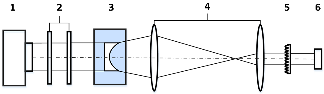
Sketch of the SHS-based wavefront measuring system. 1. Laser, 2. Polarizer pair, 3. Plano-concave lens in matching liquid, 4. Telescope lens, 5. Microlens array, 6. CCD camera.
3. Injection Molding FEM Simulation
The numerical simulation was conducted using the same condition settings identified in injection molding experiments. A 3D geometric model with plano-concave shape was meshed by using HyperMesh, as demonstrated in Fig. 4, and then imported to Moldex3D to perform FEM simulation. Except for the lens and gate, the layouts of four cooling pipes and mold base were also added into the model to be consistent with the experiment conditions but omitted from Fig. 4 for clarity.
Fig. 4.

Meshed FEM model of plano-concave lens in Moldex3D.
In the FEM modeling, three phases of injection molding process including filling, packing, and cooling were established. The same type of PMMA (Plexiglas V825) used in experiments was selected from material database. The modified Tait model and modified Cross-WLF model were employed to describe the PVT properties and viscosity behavior of PMMA in the following equations: [11]
| (1) |
| (2) |
| (3) |
When T ≤ Tt,
| (4) |
When T > Tt,
| (5) |
| (6) |
| (7) |
where V is specific volume, P is pressure, T is temperature, η is the viscosity, γ is shear rate, and all other constant parameters are summarized at the bottom of left column and the entire right column in Table 1. When simulation was finished, the computed residual stress distribution was extracted from the calculation result files for later analysis and discussion.
4. Results and Discussion
4.1. Injection molded plano-concave lens
The plano-concave optical lenses were molded and one of the molded lenses with gate, runner, and sprue is demonstrated in Fig.5. From the figure it is clear that a complete material filling is obtained and the shape of lens is round and complete. The lens surface is clear with no defects. No visible weld line, bubbles or uneven polymer solidification was discovered on the lens surface. Two directions, parallel and transverse directions were marked on the lens and illustrated in Fig.6 for discussion next.
Fig. 5.

Photograph of an injection molded plano-concave lens (showing with gate, runner, and sprue).
Fig. 6.
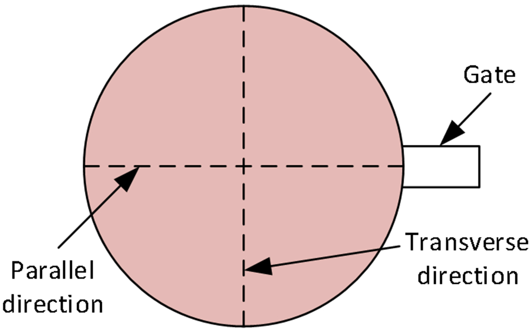
Sketch of the injection molded plano-concave lens showing two directions for observation.
4.2. Geometry and replication accuracy comparison
Since the profiles of fabricated lenses must be consistent with design to fulfill specific optical functionality, the evaluation of lens geometry is significant in optical fabrication. To measure the shape profiles and material shrinkage of the molded plano-concave lenses by both types of molds, a non-contact profilometer (Wyko NT 9100 white light profilometer) was adopted to extract the profile data of lenses in the two directions outline in Fig. 6. Due to the limitation of profilometer for large curve of the lenses in this study, Fig. 7 (a) and (b) plot the profiles of the lens central parts with a diameter of 8 mm by both graphene coated fused silica molds and aluminum molds along parallel and transverse directions, respectively. Several close up views of profile curves presenting the deviation of edge and near the vertex of the lens are also illustrated in insets. To investigate contour replication accuracy comparison between lenses and their molds, Fig. 7 (c) and (d) show the deviation of them along two directions. In the scale where we can measure, the deviation between molds and lenses can reach 10 μm for aluminum molds, but only 3 μm for graphene coated fused silica molds. We can conclude from the deviation comparison between two molds and their molded lenses that the geometry of the molded lens can be accurately determined by the aluminum molds, but the graphene coated fused silica molds has a much improved replication accuracy. Several reasons may account for this result: the main reason is the relatively small cooling rate of graphene coated fused silica molds resulted from its low thermal conductivity. The thermal conductivities for fused silica and aluminum are 1.05 W/(m2•°C) and 250 W/(m2•°C), respectively [15]. According to basic thermal dynamic equations and the dimensions of both molds, we can roughly calculate that the cooling time would be 55 s and 8 s for graphene coated fused silica molds and aluminum molds to reach temperature of 70 °C. Therefore we assumed that this would be the main reason for an improved replication accuracy. Another contributing reason might come from the different thermal expansion properties of two materials. Linear temperature expansion coefficients for aluminum and fused silica are 21~24×10−6 (m/(m K)) and 7.9×10⁻⁶ (m/(m K)), respectively [16]. Aluminum tends to expand much more than fused silica at elevated temperature and if so we can redesign the mold to compensate for the amount of expansion for aluminum molds. With a steady holding pressure applied on the molds during cooling, the replication condition between molds and polymer will not change with the thermal expansion and cooling shrinkage of the molds. We believe that the mold materials with different thermal expansion coefficients will affect replication accuracy albeit the effects are limited. Therefore, a less polymer shrinkage can be achieved when graphene coated fused silica molds are adopted.
Fig. 7.
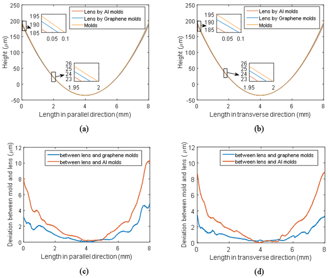
Central cross-section contours comparison among graphene coated fused silica mold, aluminum mold and their molded lens in both (a) parallel direction and (b) transverse direction. Height deviation comparison between graphene coated fused silica and aluminum molds and their lenses in both (c) parallel direction and (d) transverse direction.
4.3. Residual stresses evaluation
Residual stresses in optical elements, especially for transparent optical products, primarily influence the properties of injection molded products and may result in shrinkage and warpage of the part [17]. In this paper, a PS-100-SF polarimeter (Strainoptics Inc., North Wales, PA) was employed to measure the normalized residual stress distributions in the plano-concave lenses molded by graphene coated fused silica molds and aluminum molds. In the measuring process, the plano-concave lens was first placed on the polarimeter platform and the analyzer was then rotated until a fringe was centered on each point of interest. Thus, we could obtain normalized residual stress distributions of molded plano-concave lenses which are plotted in Fig 8 (a) and (b). It was found that the fringes became much darker on the edge of the lenses molded by graphene coated fused silica molds compared with the lenses molded by aluminum molds and the stresses exhibit more uniform in Fig 8 (a) than in Fig 8 (b). This observation demonstrates that the residual stresses can be lowered and evenly distributed by replacing conventional injection molds with the graphene coated fused silica molds.
Fig. 8.
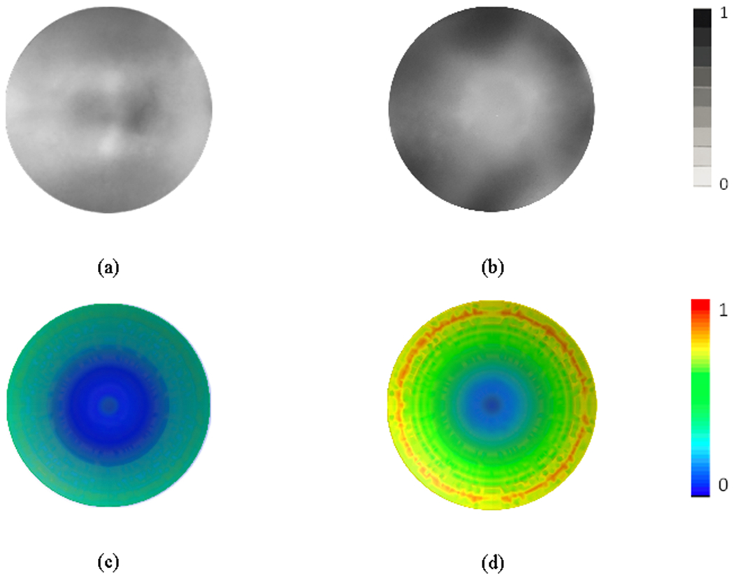
The normalized residual stress distributions of the molded plano-concave lenses by (a) (c) graphene coated fused silica molds and (b) (d) aluminum molds. (a) and (b) are measured results under a plain polariscope, (c) and (d) are simulated results by FEM software Moldex3D.
To further verify the stress distribution of the two lenses by different molds, an FEM model was established in Moldex3D. However, since there is no option for mold material setting in Moldex3D, we have to calculate the possible change of process parameters resulted from the change of mold material and input it to the model. We believe that the most significant reason graphene coated fused silica molds prevails over aluminum molds is that graphene coated molds promoted smoother polymer flow in filling phase and reduced cooling rate in cooling phase. According to previous calculations, a cooling time of 8 s and 55 s for graphene coated fused silica molds and aluminum molds was added in the model to achieve a release temperature of 70 °C. For filling time, we believe the process with graphene coated fused silica molds will need much less time in filling phase but an exact value is difficult to determine, so this value was not changed in the model. When the simulation calculation was completed, the normalized stress distribution of the lenses molded by graphene coated fused silica molds and aluminum molds are presented in Fig 8 (c) and (d).
To quantitatively investigate the intensity of the stresses in the molded lenses, Fig. 9 presents both the measured and calculated normalized residual stress intensity within lenses molded by both graphene coated fused silica molds and aluminum molds. We can see that the calculated and measured results agree with each other well for two molds but discrepancies appeared near the center part of the lenses, which might be attributed by lack of consideration of the filling time difference between two processes.
Fig. 9.

The measured and simulated residual stress intensity comparison of the molded plano-concave lenses by graphene coated fused silica molds and aluminum molds.
4.4. Reconstructed wavefront and refractive index variation
Using the SHSWS-based wavefront measurement system, the wavefront variation distributions of the plano-concave lenses injection molded by graphene coated fused silica molds and aluminum molds measured and reconstructed. Fig. 10 (a) and (b) present the reconstructed wavefront variations for the lenses molded by both the new and conventional molds in the same scale, respectively. For both lenses, the flow direction is from the right of the figure to the leftmost end along the parallel direction. It is clearly noted that using different molds, the wavefront variation patterns present great differences. When utilizing graphene coated fused silica molds, the overall wavefront variation has a smaller value than the aluminum molds. For the graphene coated fused silica molds the wavefront variations around the edge region are higher than in the central region. Specifically, the maximum wavefront variation is discovered at the areas near the far end and two outer sides of the flow direction. However, this is not the case with aluminum molds. When changing graphene coated fused silica molds to aluminum molds, the wavefront exhibits relatively clear central symmetry going up from the center to outer edges.
Fig. 10.
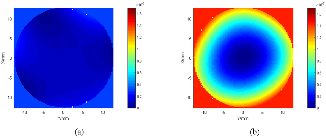
The wavefront variation in injection molded plano-concave PMMA lenses by (a) graphene coated fused silica molds and (b) aluminum molds.
The different wavefront distributions can be closely associated with different refractive index distributions [18], and any refractive index variation must have been resulted from new mold material, as all other process parameters were remained unchanged in the injection molding process. Since the thickness variation was already eliminated by aforementioned matching liquid immersing measuring, we can easily obtain refractive index variations within the lenses by two types of molds in two directions based on the reconstructed wavefront information, as demonstrated in Fig. 11. It can be seen that for graphene coated fused silica molds, no obvious difference exhibits in refractive index variation in two orthogonal directions and the value maintains steady around 1.0×10⁻³. While for aluminum molds, a general symmetrical refractive index variation distribution in both directions can be observed. The measured maximum refractive index variation difference within entire lens is approximately 4.9×10⁻³.
Fig. 11.

Refractive index variation comparison of plano-concave lens between graphene coated mold and aluminum mold in both parallel and transverse directions.
5. Conclusions
This paper demonstrated a novel injection molding of plano-concave lens with graphene coated fused silica mold inserts. Unlike conventional metal based mold such as aluminum or stainless steel injection mold material, the unique combination of graphene coating and fused silica substrate exhibits advanced properties such as low surface friction and good heat preservation effect. The injection molding experiments with both graphene coated fused silica molds and aluminum molds were carried out. As a comparison, aluminum molds were diamond machined to the same profile and size with the graphene coated fused silica molds and tested under the same molding conditions. When plano-concave lenses molded by both molds were obtained, their replication accuracy, residual stresses distribution and reconstructed wavefront were analyzed and compared. It was discovered that the new graphene coated fused silica molds prevail over conventional aluminum molds in many aspects we inspected. Furthermore, a simulation model by Moldex3D was employed to model stress distributions of both graphene and aluminm molds and then validated by experiments. The comparison between graphene coated fused silica molds and aluminum molds demonstrated that the novel injection molding with new mold inserts is a more suitable process to fabricate high quality optical lenses. The same mold material combination can also be applied to optical injection molding for microstructures or grating arrangements with less material shrinkage and residual stress, and more uniform refractive index distribution.
Acknowledgments
This study was partially based on the work supported by National Science Foundation under Grant Number 1263236. Any opinions, findings, and conclusions or recommendations expressed in this material are those of the authors and do not necessarily reflect the views of the National Science Foundation. The authors would also like to acknowledge support of an NSF SBIR Phase I and Phase II program from Nanomaterial Innovation LLC under the Grant Number 1456291. The work was also supported by National Key Basic Research Program of China (No. 2015CB059900). Xiaohua Liu acknowledges the financial support from China Scholarship Council.
References:
- 1.Zhang Hao, Scheiding Sebastian, Li Lei, Gebhardt Andreas, Risse Stefan, Eberhardt Ramona, Tünnermann Andreas, and Y Allen Y.. Manufacturing of a precision 3D microlens array on a steep curved substrate by injection molding process. Advanced Optical Technologies 23 (2013): 257–268. [Google Scholar]
- 2.Matsuoka Takaaki, Takabatake Jun-Ichi, Koiwai Akihiko, Inoue Yoshinori, Yamamoto Satoru, and Takahashi Hideroh. Integrated simulation to predict warpage of injection molded parts. Polymer Engineering & Science 3114 (1991): 1043–1050. [Google Scholar]
- 3.St Michael. Jacques. An analysis of thermal warpage in injection molded flat parts due to unbalanced cooling. Polymer Engineering & Science 224 (1982): 241–247. [Google Scholar]
- 4.Hastenberg CHV, Wildervanck PC, Leenen AJH, and Schennink GGJ. The measurement of thermal stress distributions along the flow path in injection-molded flat plates. Polymer Engineering & Science 327 (1992): 506–515. [Google Scholar]
- 5.Yang Can, Huang Hanxiong, Castro Jose M., and Yi Allen Y.. Replication characterization in injection molding of microfeatures with high aspect ratio: Influence of layout and shape factor. Polymer Engineering & Science 515 (2011): 959–968. [Google Scholar]
- 6.Haken U, Humbach O, Ortner S, Fabian H. Refractive index of silica glass: influence of fictive temperature. Journal of non-crystalline solids 2651-2 (2000): 9–18. [Google Scholar]
- 7.Kakiuchida Hiroshi, Saito Kazuya and Ikushima Akira J.. Refractive index, density and polarizability of silica glass with various fictive temperatures. Japanese journal of applied physics 43.6A (2004): L743. [Google Scholar]
- 8.Fotheringham Ulrich, Baltes Andrea, Fischer Peter, Petra Höhn Ralf Jedamzik, Schenk Christian, Stolz Claudia, and Westenberger Gerhard. Refractive index drop observed after precision molding of optical elements: a quantitative understanding based on the Tool–Narayanaswamy–Moynihan model. Journal of the American Ceramic Society 91.3 (2008): 780–783. [Google Scholar]
- 9.Su Lijuan, and Yi Allen Y.. Finite element calculation of refractive index in optical glass undergoing viscous relaxation and analysis of the effects of cooling rate and material properties. International Journal of Applied Glass Science 33 (2012): 263–274. [Google Scholar]
- 10.Yang Can, Su Lijuan, Huang Chunning, Huang Hanxiong, Castro Jose M., and Yi Allen Y.. Effect of packing pressure on refractive index variation in injection molding of precision plastic optical lens. Advances in Polymer Technology 301 (2011): 51–61. [Google Scholar]
- 11.Li Likai, Raasch Thomas W., and Yi Allen Y.. Simulation and measurement of optical aberrations of injection molded progressive addition lenses. Applied optics 5224 (2013): 6022–6029. [DOI] [PubMed] [Google Scholar]
- 12.He Peng, Li Lei, Yu Jianfeng, Huang Wenyi, Yen Ying-Chieh, L. James Lee, and Allen Y. Yi. Graphene-coated Si mold for precision glass optics molding. Optics letters 3814 (2013): 2625–2628. [DOI] [PubMed] [Google Scholar]
- 13.Huang Wenyi, Yu Jianfeng, Kwak Kwang Joo, Gallego-Perez Daniel, Liao Wei-ching, Yang Hao, Ouyang Xilian, Li Lei, Lu Wu, Lafyatis Gregory P., and Lee L. James. Atomic carbide bonding leading to superior graphene networks. Advanced Materials 2533 (2013): 4668–4672. [DOI] [PubMed] [Google Scholar]
- 14.Zhou Wenchen, Raasch Thomas W., and Yi Allen Y.. Design, fabrication, and testing of a Shack–Hartmann sensor with an automatic registration feature. Applied optics 5528 (2016): 7892–7899. [DOI] [PMC free article] [PubMed] [Google Scholar]
- 15. https://www.engineeringtoolbox.com/thermal-conductivity-d_429.html.
- 16. https://www.engineeringtoolbox.com/linear-expansion-coefficients-d_95.html.
- 17.Choi Du-Soon, Im Yong-Taek. Prediction of shrinkage and warpage in consideration of residual stress in integrated simulation of injection molding. Composite Structures 471-4 (1999): 655–665. [Google Scholar]
- 18.Yang Can, Yin Xiaohong, Castro Jose M., and Yi Allen Y.. Experimental investigation of the mold surface roughness effect in microinjection molding. Applied Mechanics and Materials. Vol. 138 Trans Tech Publications, 2012. [Google Scholar]