

Abstract
Applications of luminescent quantum dots require the materials to be stable under a wide range of temperatures, photon fluxes and chemical environments. In this work, we demonstrate that Al2O3 shells synthesized by atomic layer deposition on films of CdTe quantum dots are effective to prevent chemical degradation for up to 17 hours under continuous illumination at 90 °C in ambient air. Control samples with no Al2O3 coating experienced extensive oxidation and severe quenching of the photoluminescence intensity under these conditions.
Photoluminescent quantum dots (QDs) are actively being explored to red-shift photon wavelength for a variety of applications due to their brightness, narrow emission spectrum and tuneable emission colour. For example, QDs are at various stages of research and development in applications such as flat panel displays to increase colour richness,1 phosphor-converted light-emitting diodes (LED) for solid state lighting to tailor the spectrum of emitted light and make it more pleasing to the human eye,2 and in biomedical imaging.3 These applications require the QDs to be placed in environments that have widely varying chemical makeup, photon flux, and operational temperature. Stability is essential. For example, in the phosphor-converted LED application, solid films of QDs may experience extended periods of relatively high temperature and high photon flux, conditions under which these materials are known to degrade.4 Protocols exist for accelerated lifetime measurement. For example, the LM-80 standard requires that LED devices be subjected to 85 °C in air with high relative humidity for accelerated lifetime measurement.5 Most research has been performed at room temperature in an inert environment. It is therefore uncertain how these materials will behave under the aggressive conditions required by the above applications.
The most common strategy to make quantum dots more robust is to grow an epitaxial inorganic chalcogenide shell on the surface, typically CdS, ZnS, or combinations thereof.4b,6 The shell can then be further modified, for example with siloxane, to increase compatibility with biological systems.7 However, after extended periods of time at high temperature in the presence of water and oxygen, or extended periods of time under high photon flux, even QDs with chalcogenide shells exhibit unacceptable decline of photoluminescence (PL) quantum yield.4,8 We propose that metal oxides provide better protection than chalcogenide shells. For example, it is known that cation diffusion is fast in metal-sulfides9 compared to metal-oxides.10 Cations can diffuse from the core, through the chalcogenide shell, to the surface to react with oxygen or water. Since solid state diffusion coefficients in metal-oxides are often many orders of magnitude smaller than in metal-sulfides,9b,10 metal-oxides may be superior for protecting the QD core from (photo)chemical degradation. Indeed, promising early results have been reported.4a There is a need to develop robust, scalable methods to coat nanocrystals with high-quality metal-oxide shells.
Atomic layer deposition (ALD) is a layer-by-layer gas-phase coating process that offers exceptional uniformity on nano-structured substrates such as nanocrystals.11 ALD processes operate by introducing two complimentary volatile chemical precursors into the reactor in a sequential fashion with purge steps in between. The deposition of Al2O3 is well understood.11,12 Al2O3 deposited by ALD is amorphous. The process proceeds by first pulsing trimethylaluminum (TMA) into the chamber. The TMA reacts with surface hydroxyl, releasing methane, until the entire substrate surface is saturated with chemisorbed methyl aluminium species, at which time the surface reaction stops. The hydroxyl species can be water adsorbed on a metal oxide surface, or it can be associated with the functional group of an adsorbed organic molecule.13 The excess unreacted TMA is then purged from the reactor. The second chemical reaction proceeds by pulsing H2O through the reactor, which reacts with the chemisorbed methyl aluminium to form chemisorbed hydroxyl, until the entire surface is saturated and the reaction stops. Excess water is then purged from the reactor. One cycle deposits one submonolayer of aluminium oxide. This process: pulse TMA, purge TMA, pulse H2O, purge H2O; can be repeated many times to build up a coating with control over thickness at the angstrom length scale. Ideally all surfaces wetted by the process gases receive the same amount of deposition, and the coatings are conformal. ALD processes can be scaled up to coat large quantities of nanoparticles, for example using a fluidized bed configuration.14 A number of authors have demonstrated that ALD is an effective tool to stabilize nanomaterials.15 However, to our knowledge, ALD has not been studied as a means to stabilize photoluminescent QDs.
In this communication, we report our first results on the use of ALD to stabilize photoluminescent QDs against chemically aggressive environments. Specifically, 3.6 nm diameter, carboxyl-capped CdTe QDs were coated with a 20 nm shell of Al2O3 by ALD. These Al2O3-coated CdTe QDs were then heated to 90 °C in ambient air for 17 hours under continuous illumination, while monitoring the PL. It was found that Al2O3-coated QDs retained 94% of the initial PL quantum yield after the heat treatment; while control QDs with only carboxyl termination degraded to 33% of the initial PL quantum yield. X-ray photoelectron spectroscopy (XPS) revealed that the Al2O3 shell effectively prevented oxidation of the CdTe core, while the QDs without Al2O3 shell were extensively oxidized.
Solid samples were used for this study to ensure good contact between the QDs and ambient air at the elevated temperature used during stability testing. Detailed sample preparation procedures can be found in the ESI.† Water soluble CdTe QDs with nominal PL emission at 610 nm, which were 3.6 nm in diameter and passivated by short chain thiocarboxylic acid (HS-R-COOH) ligands, were purchased from Sigma-Aldrich (P/N: 777951) and used as-received without further purification. Thiol groups were bound to the surfaces of the nanocrystals, while the carboxylic groups presented to the external environment. The carboxyl termination is necessary to initiate ALD of Al2O3, which involves the reaction of TMA with hydroxyl.12a,13 The QDs were dispersed in an isopropanol/water solution and drop-casted onto glass microscope slides to form a solid sample (Fig. 1c). The resulting films were approximately 4 micrometres in thickness, as determined by profilometry. The drop-casting procedure resulted in a slight redshift of the PL wavelength to approximately 640 nm for some of the samples. The drop-casted QD films were coated with Al2O3 using the well-known process that has been reported in the literature.12a,16 In Fig. 1, a representative transmission electron microscopy (TEM) image of the ALD-coated nanocrystals and digital images of as-prepared solid samples are presented. In Fig. 1b, it can be seen that the Al2O3 forms a conformal shell around the core, which appears to contain several QDs. The temperature at which ALD was carried out was found to play an important role. Samples were coated using the same precursor pulse times (1 second) and purge times (60 seconds), at different deposition temperatures. PL spectra were measured before and after the ALD coating procedure. It was found that coating nanocrystals at high temperature resulted in significant quenching of the PL (ESI,† Fig. S1).
Fig. 1.

(a) Schematic of CdTe QDs coated with Al2O3. (b) TEM image of CdTe QDs coated with 20 nm of Al2O3 by ALD using the same conditions as Fig. 2. The scale bar in (b) is 50 nm. (c) Digital photograph of a drop-casted QD film under room light. (d) Digital photograph of a drop-casted film under illumination by a 390 nm LED lamp.
The PL intensity after the ALD coating procedure, normalized by the initial intensity, was highest for samples coated at low temperature (ESI,† Fig. S1). We currently speculate that the quenching of PL for samples coated by ALD at high temperature resulted from desorption of a fraction of organic surface ligands in the vacuum, but work in our laboratory is ongoing to explain this observation. ALD Al2O3 deposited using the TMA-and-H2O process at low temperature is known to have significant hydroxyl impurity content,12a which is correlated to higher water vapour transmission rate.17 Thus, there is a compromise in selecting the ALD temperature. Less PL quenching was observed for low temperature ALD processes, however shells deposited at higher temperatures are expected to be higher quality. The sample used for stability testing was first coated with 10 nm of alumina at 50 °C, and then coated with an additional 10 nm of alumina at 150 °C to form a high quality outer shell. The stabilizing effect of the Al2O3 shell can be seen first in this experiment. A core-only sample coated with 10 nm of Al2O3 at 150 °C retained 18% of its initial PL intensity, however a sample coated first at 50 °C with 10 nm of Al2O3, and subsequently with 10 nm at 150 °C using the same conditions, retained 35% of the initial PL intensity before any ALD coating. Furthermore, coating the CdTe QDs first at 50 °C with 10 nm of Al2O3, and then at 150 °C with 10 nm of Al2O3, resulted in better thermal stability compared to 20 nm at lower temperature (ESI,† Fig. S2). It is expected that the Al2O3 shell could be optimized by dynamically ramping the temperature during the deposition process, from near room temperature to above 100 °C. However, such optimization is beyond the scope of this communication. Alternatively, we surmise that a chalcogenide “soft-shell”, such as ZnS or CdS, could be used to temporarily stabilize the core during deposition of the “hard-shell” of Al2O3; provided the soft-shell had surface termination with hydroxyl or carboxyl functional groups to initiate the ALD reaction.
The stability of the films was tested by the following photothermal soaking experiment. Details can be found in the ESI.† Two samples, one core-only with carboxyl termination, and the other coated with 10 nm of alumina at 50 °C, and 10 nm of alumina at 150 °C, were placed next to each other on a hot plate at a temperature of 90 °C in the laboratory ambient (Fig. 2). The sample temperature was measured by an infrared thermometer. Under illumination of the top surface at a wavelength of 420 nm, the PL intensity was monitored as a function of time for approximately 17 hours, using a 2D detector from a quantitative CCD camera fitted with a 550 nm long pass filter. The PL intensity was calculated by integrating the intensity over the area occupied by the sample in the image, and subtracting the baseline intensity from adjacent regions that contained no QDs. The intensity was normalized by the initial value to quantify relative changes in quantum yield. The temperature of 90 °C was chosen to match the LM-80 standard. The time duration of 17 hours was sufficient to demonstrate the protective effect of ALD treatment. Following 17 hours under illumination at 90 °C in air, the samples were allowed to cool at a controlled rate back to ambient temperature. The PL intensity was monitored during the cooling period to quantify any reversible changes that may have occurred simply due to temperature.
Fig. 2.
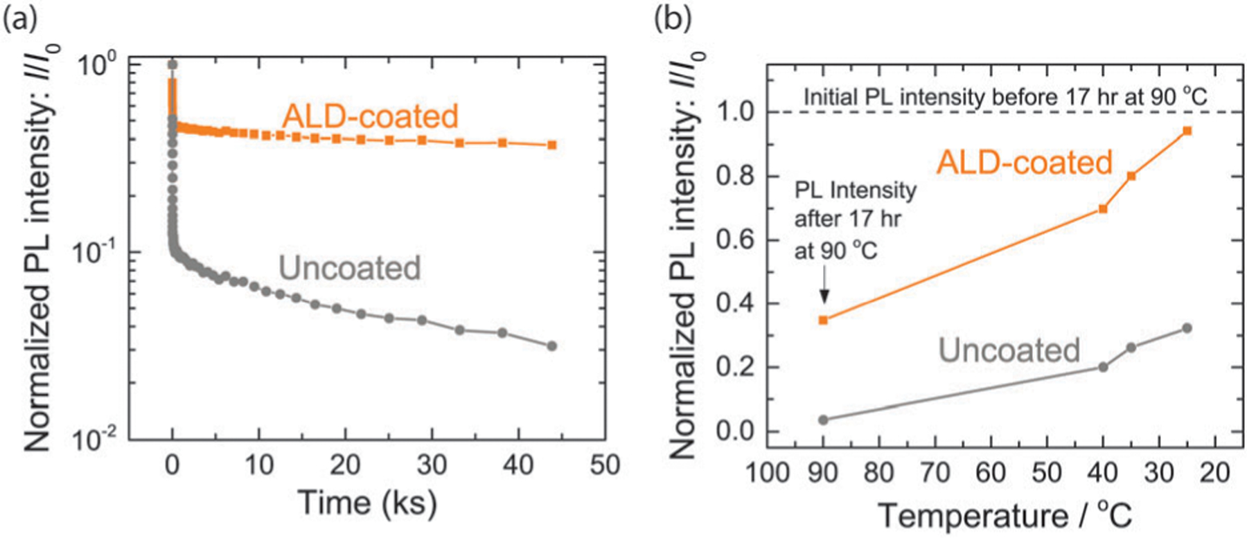
(a) Normalized PL intensity as a function of time at 90 °C under continuous illumination for two CdTe QD samples, with and without ALD Al2O3 coating. (b) Normalized PL intensity, taken after holding for 17 hours at 90 °C, as the samples cooled back to room temperature. The intensity in (a) and (b) was normalized by the room temperature PL intensity I0 measured immediately before the photothermal soaking experiment.
The PL intensity of CdTe QDs with an Al2O3 shell was more stable compared to the uncoated core-only control. Plotted in Fig. 2a is the normalized PL intensity as a function of time for nanocrystals held at 90 °C with, and without, an ALD alumina shell. The values were normalized by the initial room temperature PL intensity of that sample before any stability testing. Both the coated and uncoated samples showed a very rapid decrease in intensity that occurred in less than 1.0 kiloseconds (ks). The initial decrease in PL intensity is attributed to the effect of temperature on the exciton dynamics.18 In the temperature range from 100 K to 360 K, the exciton lifetime in CdTe QDs monotonically decreases with increasing temperature as dark recombination process become more competitive,18 and thus, the PL quantum yield decreases with increasing temperature. If no chemical or structural transformation has taken place, then the effect is expected to be reversible when the sample cools. As the samples were held for longer times at 90 °C in ambient air, the PL intensity of the uncoated QDs showed a long term decrease, which is attributed to oxidation of the CdTe (vide infra). The ALD-coated QDs were relatively stable over long time scales (Fig. 2a). After completion of the extended hold at 90 °C in air under illumination, the samples were slowly cooled back to room temperature. At a few intermediate points during cooling, the temperature was allowed to stabilize and PL intensity maps were acquired. The PL intensity increased as the samples cooled (Fig. 2b). The ALD-coated sample returned to nearly the initial value, suggesting that nearly all of the decrease in PL intensity could be attributed to the reversible effect of temperature on the exciton lifetime. The uncoated sample, however, only returned to approximately 33% of the initial PL intensity.
The CdTe of the uncoated sample became oxidized during the stability experiment, which presumably caused the irreversible decrease in PL intensity illustrated in Fig. 2. The ALD-coated sample did not oxidize significantly, however, hence the improved PL stability. XPS spectra were acquired as a function of depth into the samples during ion milling (Fig. 3). The depth into the sample is reported as sputtering time. Increasing sputtering time corresponds to increasing depth into the sample. The uncoated sample displayed extensive oxidation of both Cd and Te on the surface, while the composition of QDs deeper into the sample remained as CdTe (Fig. 3a, c and e). We estimate the sputtering rate to be approximately 0.5 nm s−1 for the uncoated CdTe film. The CdTe films were several micrometres thick, and XPS spectra show that the oxidation of the uncoated CdTe QDs after photothermal soaking is significant in the top 100 nm of the film. After the uncoated CdTe QDs had been soaked photothermally, the PL spectra blue shifted, consistent with partially oxidised QDs smaller in size (ESI,† Fig. S3). Previous measurements of the absorption coefficient19 for CdTe at 420 nm indicate that the absorption depth in nanocrystalline CdTe is approximately 33 nm. Thus, the small amount of light that is able to pass through the oxidized layer can excite unoxidized QDs deeper in the film. We hypothesize that the uncoated sample was photochemically oxidized4b during extended illumination at high temperature in air, which would explain why the oxidation dropped off rapidly with increasing depth into the film. However, further work is required to prove the oxidation mechanism. For the ALD-coated sample, no Cd or Te was visible on the surface (Fig. 3b, d and f). Thus the Al2O3 coating was pinhole free, at least to the sensitivity of XPS. At a depth corresponding to a sputtering time of approximately 400 s, both Cd and Te became visible, and there were no signs of oxidation (Fig. 3b, d and f). No carbon was observed in the Al2O3 coating. However, significant intensity from the C 1s peak appeared at approximately the depth where CdTe was reached. From this observation, we tentatively conclude that some fraction of the organic ligands on the surfaces of the CdTe QDs remained after the ALD coating process. This is consistent with the ALD process initiating by reaction of TMA with carboxyl functional groups.
Fig. 3.

XPS characterization of the uncoated sample (a, c and e) and ALD-coated sample (b, d and f) measured after the experiment in Fig. 2. (a) Fraction of Te present as oxide as a function of depth into the uncoated sample. (b) Depth profile for the ALD-coated sample. In panels (c–f), the spectra have been vertically offset for clarity. (c) Uncoated sample, Te 3d XPS spectra. (d) ALD-coated sample, Te 3d XPS spectra. (e) Uncoated sample, Cd 3d XPS spectra. (f) ALD-coated sample, Cd 3d XPS spectra.
In conclusion, herein we presented a study of the use of Al2O3 coatings deposited on CdTe QDs for oxidation resistance at high temperature under continuous illumination. After 17 hours at 90 °C under continuous illumination, CdTe QDs that had been coated with Al2O3 retained approximately 94% of their initial photoluminescence intensity. Under the same conditions, core-only CdTe QDs without Al2O3 showed a degradation of the photoluminescence intensity to 33% of the initial value. Bolstered by this successful result, there are several next steps for consideration. First, a mechanistic understanding of the ALD coating process must be developed, with the goal of suppressing PL quenching and suppressing particle agglomeration. Furthermore, the role of the terminal functional group of the ligand molecules in initiating the ALD reaction must be elucidated, so the technique can be applied to other QD core materials. Finally, it would be useful to understand the chemical mechanism of degradation for the core-only QDs. Work focused on these questions is ongoing.
Supplementary Material
Footnotes
Electronic supplementary information (ESI) available: Experimental procedures and additional experimental results.
Notes and references
- 1.Bourzac K, Nature, 2013, 493, 283. [DOI] [PubMed] [Google Scholar]
- 2.Hoppe HA, Angew. Chem., Int. Ed, 2009, 48, 3572–3582. [DOI] [PubMed] [Google Scholar]
- 3.Michalet X, Pinaud FF, Bentolila LA, Tsay JM, Doose S, Li JJ, Sundaresan G, Wu AM, Gambhir SS and Weiss S, Science, 2005, 307, 538–544. [DOI] [PMC free article] [PubMed] [Google Scholar]
- 4.(a) Li ZC, Yao W, Kong L, Zhao YX and Li L, J. Am. Chem. Soc, 2015, 137, 12430–12433; [DOI] [PubMed] [Google Scholar]; (b) Xie R, Kolb U, Li J, Basché T and Mews A, J. Am. Chem. Soc, 2005, 127, 7480–7488. [DOI] [PubMed] [Google Scholar]
- 5.LM-80–15 IES Approved Method: Measuring Luminous Flux and Color Maintenance of LED Packages, Arrays and Modules, 2016, IES. [Google Scholar]
- 6.(a) Dabbousi BO, RodriguezViejo J, Mikulec FV, Heine JR, Mattoussi H, Ober R, Jensen KF and Bawendi MG, J. Phys. Chem. B, 1997, 101, 9463–9475; [Google Scholar]; (b) Peng XG, Schlamp MC, Kadavanich AV and Alivisatos AP, J. Am. Chem. Soc, 1997, 119, 7019–7029; [Google Scholar]; (c) Reiss P, Protière M and Li L, Small, 2009, 5, 154–168. [DOI] [PubMed] [Google Scholar]
- 7.Gerion D, Pinaud F, Williams SC, Parak WJ, Zanchet D, Weiss S and Alivisatos AP, J. Phys. Chem. B, 2001, 105, 8861–8871. [Google Scholar]
- 8.Liu TC, Huang ZL, Wang HQ, Wang JH, Li XQ, Zhao YD and Luo QM, Anal. Chim. Acta, 2006, 559, 120–123. [DOI] [PubMed] [Google Scholar]
- 9.(a) Thimsen E, Peng Q, Martinson ABF, Pellin MJ and Elam JW, Chem. Mater, 2011, 23, 4411–4413; [Google Scholar]; (b) Thimsen E, Baryshev SV, Martinson ABF, Elam JW, Veryovkin IV and Pellin MJ, Chem. Mater, 2013, 25, 313–319. [Google Scholar]
- 10.Thimsen E, Martinson ABF, Elam JW and Pellin MJ, J. Phys. Chem. C, 2012, 116, 16830–16840. [Google Scholar]
- 11.George SM, Chem. Rev, 2010, 110, 111–131. [DOI] [PubMed] [Google Scholar]
- 12.(a) Groner MD, Fabreguette FH, Elam JW and George SM, Chem. Mater, 2004, 16, 639–645; [Google Scholar]; (b) Elam JW and George SM, Chem. Mater, 2003, 15, 1020–1028. [Google Scholar]
- 13.Dameron AA, Seghete D, Burton BB, Davidson SD, Cavanagh AS, Bertrand JA and George SM, Chem. Mater, 2008, 20, 3315–3326. [Google Scholar]
- 14.(a) Didden AP, Middelkoop J, Besling WFA, Nanu DE and van de Krol R, Rev. Sci. Instrum, 2014, 85, 013905; [DOI] [PubMed] [Google Scholar]; (b) King DM, Liang XH and Weimer AW, Powder Technol, 2012, 221, 13–25; [Google Scholar]; (c) King DM, Spencer Ii JA, Liang X, Hakim LF and Weimer AW, Surf. Coat. Technol, 2007, 201, 9163–9171. [Google Scholar]
- 15.(a) Paracchino A, Laporte V, Sivula K, Gratzel M and Thimsen E, Nat. Mater, 2011, 10, 456–461; [DOI] [PubMed] [Google Scholar]; (b) Martinson ABF, Riha SC, Thimsen E, Elam JW and Pellin MJ, Energy Environ. Sci, 2013, 6, 1868–1878; [Google Scholar]; (c) Riha SC, Jin S, Baryshev SV, Thimsen E, Wiederrecht GP and Martinson ABF, ACS Appl. Mater. Interfaces, 2013, 5, 10302–10309; [DOI] [PubMed] [Google Scholar]; (d) Thimsen E, Johnson M, Zhang X, Wagner AJ, Mkhoyan KA, Kortshagen UR and Aydil ES, Nat. Commun, 2014, 5, 5822; [DOI] [PubMed] [Google Scholar]; (e) Liu Y, Tolentino J, Gibbs M, Ihly R, Perkins CL, Liu Y, Crawford N, Hemminger JC and Law M, Nano Lett, 2013, 13, 1578–1587; [DOI] [PubMed] [Google Scholar]; (f) Ihly R, Tolentino J, Liu Y, Gibbs M and Law M, ACS Nano, 2011, 5, 8175–8186; [DOI] [PubMed] [Google Scholar]; (g) Pourret A, Guyot-Sionnest P and Elam JW, Adv. Mater, 2009, 21, 232–235; [Google Scholar]; (h) Liu Y, Gibbs M, Perkins CL, Tolentino J, Zarghami MH, Bustamante J and Law M, Nano Lett, 2011, 11, 5349–5355. [DOI] [PubMed] [Google Scholar]
- 16.Elam JW, Sechrist ZA and George SM, Thin Solid Films, 2002, 414, 43–55. [Google Scholar]
- 17.Jung H, Choi H, Jeon H, Lee S and Jeon H, J. Appl. Phys, 2013, 114, 173511. [Google Scholar]
- 18.(a) Nonoguchi Y, Nakashima T and Kawai T, J. Phys. Chem. C, 2008, 112, 19263–19267; [Google Scholar]; (b) Kalytchuk S, Zhovtiuk O, Kershaw SV, Zbořil R and Rogach AL, Small, 2016, 12, 466–476. [DOI] [PubMed] [Google Scholar]
- 19.Chandra S, Sundari ST, Raghavan G and Tyagi AK, J. Phys. D: Appl. Phys, 2003, 36, 2121–2129. [Google Scholar]
Associated Data
This section collects any data citations, data availability statements, or supplementary materials included in this article.