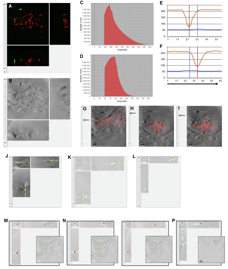
Figure S3.
Accuracy of 3D correlation, related to Figures 4 and 5
In order to assess the accuracy of our 3D rigid registration procedure, a sample with two fluorescent features (gold beads and mitochondria) was used. It has been demonstrated that real alignment error can be predicted under the assumption of a correct model (rigid model used to match rigidly linked dataset) (Paul-Gilloteaux et al., 2017). We used this error prediction facility in eC-CLEM to assess correlated nanoparticle localization in both imaging modalities used (cryoSIM and cryoSXT). In (A) are orthogonal views of the 3D registered SIM dataset (green channel: Au 150 nm beads coated with Alexa488; red channel: mitochondria stained with Mitotracker red). The scale bars shown on XY views, apply in ZX and YZ views also (the generated data are isotropic with voxel size of 10x10x10 nm). Note that tomogram tilting shown in (B), was taken into account during 3D registration. In (B) are orthogonal views of the associated 3D X-ray tomogram used as target volume for 3D registration. The source volume was the pre-aligned 3D SIM dataset relocated in 2D as described in Figure 5. In (C) is the distribution of error when using only 5 beads (fewer points, localized within the SIM resolution) for the registration of the 9 beads visible in total within the fluorescence signal of this volume. This distribution is obtained by taking the histogram of the predicted average error of eC-CLEM error map which has been validated in Paul-Gilloteaux et al. (2017), but was checked against the beads here. X axis is the registration error, y axis is the number of voxels in this volume with this error. The error range (in 3D) was found to be between 80 and 500 nm, with 95% of the error below 350 nm, and 50% under 150 nm. In (D) is the distribution of error when using 15 unique points on mitochondria (more points, less accurately localized) for the registration. x axis is the registration error in nm, y axis is the number of voxel in this volume with this error. The error range (in 3D) was found to be between 50 and 300 nm, with 95% of the error below 130 nm, and 50% under 85 nm. In (E) and (F) are 2D line profiles along two beads (shown in J and K) in XY after overlay of 3D registered SIM and X-ray tomogram data. The orange line plot is the bead intensity profile in the X-ray volume and the blue line is the profile of the same bead in the 3D registered interpolated fluorescent data. The distance between the peaks of fluorescent signal and X-ray signal give an indication of the positional discrepancy in 2D of that bead. x axis is in pixels (1 pixel = 10 nm), y axis is the 8-bit converted intensity for X-ray and fluorescence signal. (G) (I) show 3 different slices of the 3D SIM-registered signal on their respective target X-ray positions. The superimposition of mitochondrial red signal on the visible X-ray mitochondrial trace show that the 3D rigid model used was correct, and the sample did not undergo any significant deformation. Scale bar is 1 μm. In (J–L) is a superimposition of the 3D-registered SIM green channel on the X-ray tomogram, cropped around beads used for the registration. Note that the beads have been tilted in the 3D SIM to match the tilt of the X-ray volume. Scale bar is 1 μm and is valid for XY and YZ representations. In (M–P) is the cropped area in orthoviews of the four beads not used for the registration. Each bead position is indicated in the bottom right 2D insert of the full FOV of the X-ray tomograph to highlight their relative distribution in the sample. As can be seen in particular for (N) and (P), the 3D discrepancy has to be considered to supplement 2D profile representations. Scale bar is 100 nm when not indicated.

