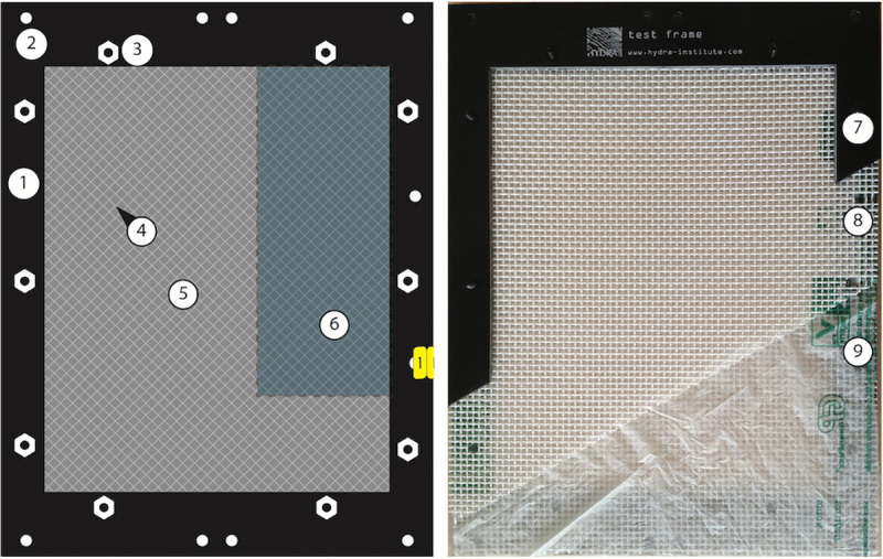
Fig 1. HYDRA test frame.

Left panel: Scheme of test frame. (1) upper frame, (2) holes for fixing the frame to sample holders, (3) plastic nuts, (4) mesh covering the test material, (5) test material (film), (6) area for subsamples. Right panel: photo of HYDRA test frame, cut open to show different layers. (7) upper frame, (8) upper protective polyester mesh (modified to 2 x 2 mm), (9) test material (plastic bag), seen through film: lower mesh, lower frame.
