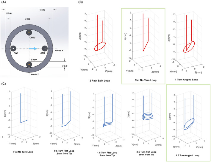
FIGURE 2.

Design of the shim coils. A, Solidworks sketch of two example shim coils in the needle’s coordinate frame. All dimensions are in mm. CN0 and CN90 are designed orthogonally with the angle representing the coil’s deviation from the needle’s Y axis (blue arrow). Only one angle is used to define the coils in the needle frame, since all coils are designed orthogonal to the needle’s radial plane. X and O represent directions of current flow. B,C, 3 CN0 (red) and 5 of the 21 CN90 (blue) paths considered for optimization are shown. All coils are shown in the magnet coordinate frame with orientation (0, 0, 0). The complete set of coils is shown in Supporting Information Figure S1. Green boxes highlight the pair of coils chosen for the optimized shim set
