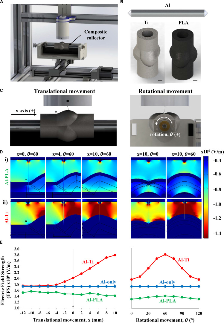
FIGURE 1.
Simulation of the electric field strength (EFS) (V/m) established between the spinneret and aortic root model during MEW. (A) Schematic representation of the mounted collector onto a standard MEW device. (B) Aluminum only (Al-only), Al-titanium (Al-Ti) and Al-polylactic acid (Al-PLA) mandrel models used for electric field simulation (scale bar = 5 mm). (C) Front (left) and side (right) plane views of the MEW setup used in this study, * indicates the point on the mandrel where x = 0 (D) Heat maps showing the EFS distribution when printing on i) Al-PLA and ii) Al-Ti collectors at different stages of the translational (left) and rotational (right) movements, (E) Quantitative EFS simulation results when printing on the different double component collectors: Al-Ti (red), Al-PLA (green) and Al-only (blue).

