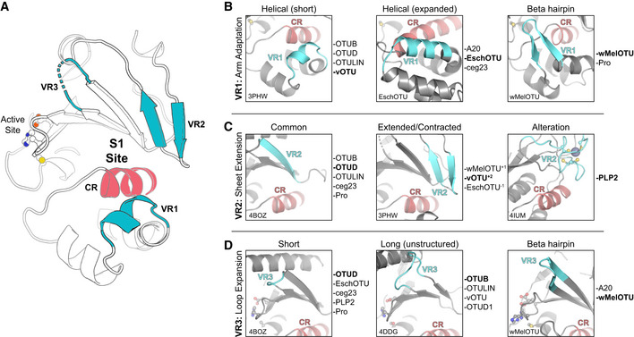
Figure 6. A framework for understanding the S1 site of OTU domains.

-
ACartoon representation of the OTU fold (vOTU, PDB 3PHW), with the active site and S1 site indicated. The S1 site is composed of a common region (CR, red) surrounded by three variable regions (VR, blue) that are responsible for Ub binding.
-
BComparison of structural adaptations in the VR1 arm region of the S1 site. VR1 has been observed to contribute to Ub binding as either a short α‐helical segment (left), an extended α‐helical region (center), or a β‐hairpin (right). Examples of OTUs that follow each arrangement are provided to the right.
-
CComparison of structural adaptations in the VR2 central β‐sheet edge of the S1 site. VR2 has been observed to contribute to Ub binding in its most common arrangement (left), with additional or fewer β‐strands (center), or altered with additional substructure (right). Examples of OTUs that follow each arrangement are provided to the right.
-
DComparison of structural adaptations in the VR3 loop extending from the central β‐sheet. This VR3 loop has been observed as short and not utilized in Ub binding (left), expanded and participating in unstructured interactions with Ub (center), or expanded with a β‐hairpin motif that binds Ub (right). Examples of OTUs that follow each arrangement are provided to the right.
