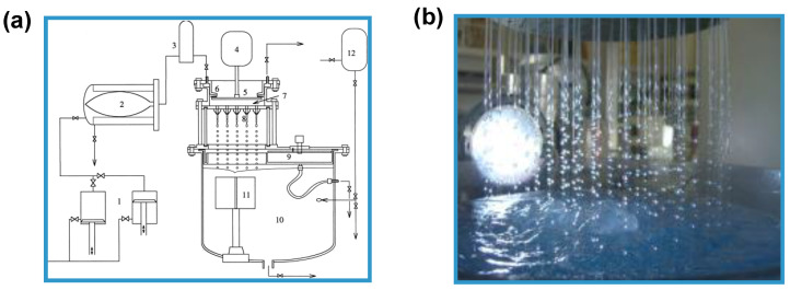
Figure 5.
(a) Schematic illustration representing a multi-nozzle encapsulator (1, double piston pump; 2, sterile barrier; 3, damper; 4, vibrator; 5, membrane of pulsation chamber; 6, concentric split; 7, pulsation chamber; 8, nozzle plate; 9, bypass system; 10, reaction vessel; 11, stirrer; and 12, input hardening solution). Reprinted from [26] with permission from Elsevier. Copyright (1998). (b) Picture showing the equipment supplied by Brace GmbH (https://www.brace.de).

