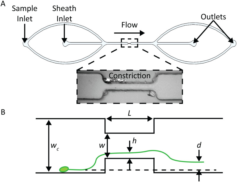
FIG. 4.
(a) Diagram of constriction device, indicating the location of sample and sheath inlets (inset: bright field image of constriction region in the microchannel). (b) Illustration of constriction device indicating key geometric and measurement variables. Variable is the distance of the particle to the wall within the constriction, and is the particle displacement.

