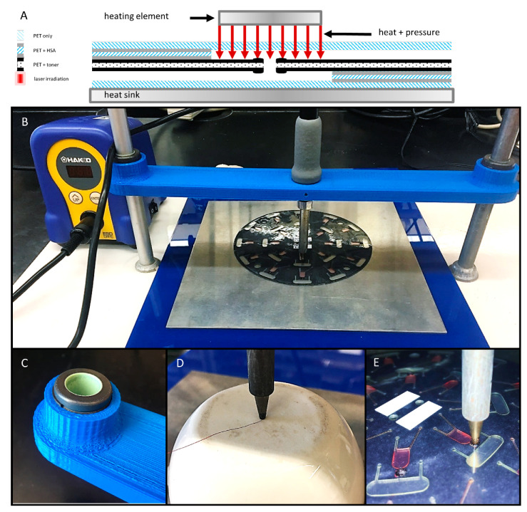
Figure 3.
Schematic diagram and photographs of the gantry platform for bringing the heating element into contact with the disc. (A) Schematic diagram of the contact heating approach. (B) A gantry arm was 3D printed, outfitted with two self-aligning linear sleeve bearings (C), and suspended between two standard laboratory support stands. The soldering stylus was inserted into the gantry arm, held in place with set screws, and connected to the adjustable power supply. (D) Calibration of stylus temperature with a digital thermometer and a T-type thermocouple. (E) Close-up photograph of the soldering stylus in contact with a previously opened laser valve (2 × 2 mm).

