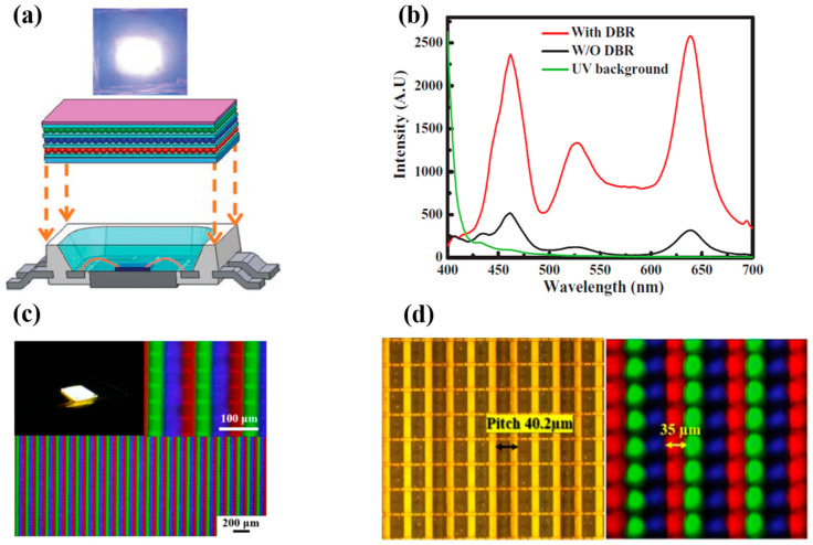
Figure 1.
(a) Schematic of QD-LED device (bottom). Photograph of the QD-LED during operation (top). (b) EL spectra with and without the DBR structure. (c) Image of sprayed QDs μLED array under fluorescence microscopy at different magnifications. (d) Top-view image of the μLED layout with pitch of 40.2 μm defined as the intended channel (left). Quantum dots (QD) droplets jetted in the PR mold to confine the size and resolve the cross-talk effect (right) [44]. Figure reproduced with permission from John Wiley and Sons.

