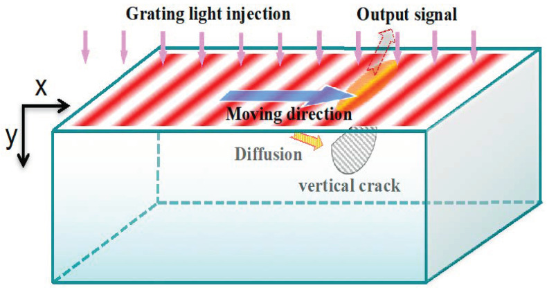
Figure 3.
Illustration of infrared grating thermal wave scanning method. The red stripes represent the light gratings, they move from left to right along x direction. The light gratings generate heat flux at the surface and thus thermal waves form at the surface correspondingly. When the thermal waves meet cracks or defect, they will be reflected and will further propagate to the surface. By monitoring the temperature signals of the surface, the cracks can be detected.

