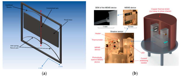
Figure 4.
Schematic diagrams of MEMS accelerometer and experimental setup developed by Middlemiss et al. at University of Glasgow [17]: (a) schematic diagram of the MEMS accelerometer—central proof mass was suspended from three flexures: an anti-spring pair at the bottom and a curved cantilever at the top; (b) experimental setup. (Figure 4a is redrew by the authors)

