Abstract
The development of simple detection methods aimed at widespread screening and testing is crucial for many infections and diseases, including prostate cancer where early diagnosis increases the chances of cure considerably. In this paper, we report on genosensors with different detection principles for a prostate cancer specific DNA sequence (PCA3). The genosensors were made with carbon printed electrodes or quartz coated with layer-by-layer (LbL) films containing gold nanoparticles and chondroitin sulfate and a layer of a complementary DNA sequence (PCA3 probe). The highest sensitivity was reached with electrochemical impedance spectroscopy with the detection limit of 83 pM in solutions of PCA3, while the limits of detection were 2000 pM and 900 pM for cyclic voltammetry and UV–vis spectroscopy, respectively. That detection could be performed with an optical method is encouraging, as one may envisage extending it to colorimetric tests. Since the morphology of sensing units is known to be affected in detection experiments, we applied machine learning algorithms to classify scanning electron microscopy images of the genosensors and managed to distinguish those exposed to PCA3-containing solutions from control measurements with an accuracy of 99.9%. The performance in distinguishing each individual PCA3 concentration in a multiclass task was lower, with an accuracy of 88.3%, which means that further developments in image analysis are required for this innovative approach.
Keywords: Prostate cancer, PCA3 biomarker, Electrochemical impedance, Image analysis, Machine learning
Graphical abstract
1. Introduction
The search for new diagnostic methodologies has gained tremendous impetus with the Covid-19 pandemic outbreak in 2020, for it has become clear that low-cost, easily deployable tests are crucial for humanity. Three main challenges have to be faced to fulfill such stringent requirements: the sensing units must be cheap and easy to manufacture even in developing countries; the principle of detection should be simple without requiring highly trained personnel to operate the measuring equipment; data analysis should be robust and fast. Much has been done in all of these challenges, as can be easily confirmed in the recent literature for various types of biosensors (see e.g. some review papers) [[1], [2], [3], [4], [5]]. However, this considerable body of knowledge has not been transformed into products for various reasons, the most important of which is perhaps the high cost of device engineering to develop tests and certify them through government agencies. This is particularly the case of neglected diseases or of diseases in which the number of tests to be commercialized would not justify the large investments.
We advocate, nevertheless, that efforts should be made to develop sensing technology that is sufficiently generic to leverage progresses in different areas, across different diseases and for monitoring health conditions. Moreover, there are diseases for which such new methodologies are urgent. This applies to prostate cancer [6], which is rarely symptomatic as the tumor grows quietly and the failure to detect early makes this disease the second cause of death in men in industrialized countries [7]. Today, prostate cancer is diagnosed with a combination of a blood test to detect the prostate specific antigen (PSA) and rectal examination [8]. Unfortunately, in spite of its high sensitivity, the PSA test has low specificity, thus resulting in many negative biopsies, i.e. unnecessary and invasive procedures [9,10]. An increased PSA concentration may arise from non-cancerous conditions such as prostate infections, prostate enlargement and even recent sexual activity [11]. This state of affairs may change significantly if more specific biomarkers are found. An important candidate is the prostate cancer gene 3 (PCA3) located on the chromosome 9q21–22 [12,13], which is prostate-specific and associated with prostate cancer [[14], [15], [16], [17]]. PCA3 was identified in 1995 [18], being initially called DD3 (Differential Display Clone 3) since differential display analysis was used to compare mRNA expression patterns of normal versus prostate cancer tissues [19]. Overexpression of PCA3 gene was observed in 95% of prostate cancer samples, while gene 3 expression was not detected in any other normal or multi-organ tumor tissues. In benign altered prostate cells, very low levels of gene expression were detected [20,21]. PCA3 biomarker is specific for prostate cancer and there is no cut-off concentration. Even low concentrations of PCA3 are indicative of a high probability that a patient has (or will) developed prostate cancer.
There are a few reports of sensors to detect PCA3 [15,20,22,23] including our own recent work [22], which is the only one using a simple principle of detection to the best of our knowledge. In this study, we build upon this previous work to address the last two challenges of the three mentioned in the beginning of this introduction. More specifically, we show that genosensors can be built with simple manufacturing processes and applied with varied principles of detection. We show that PCA3 can be detected using electrochemical methods, optical absorption spectroscopy and through image analysis of the sensing devices. Furthermore, the matrix onto which the DNA sequence (PCA3 Probe) is immobilized differs from our previous work, as we incorporated gold nanoparticles along with chitosan and chondroitin sulfate to enhance the electrical signal. As for data analysis we employ information visualization techniques for the electrochemical impedance data, with which the highest sensitivity was obtained, and machine learning methods to classify the images taken from the genosensing units. The overall aim was to obtain a generic platform in terms of materials, devices and data analysis, which can be replicated to other biomarkers and other diseases.
2. Materials and methods
2.1. Fabrication and characterization of the genosensors
The genosensors were made with layer-by-layer (LbL) films [24] containing alternating layers of gold nanoparticles stabilized with chondroitin sulfate (AuNP-CS) and of the PCA3 probe designed for detection. The LbL films were deposited onto the working electrode of a commercial, 4 mm diameter printed carbon electrode (Dropsens, Spain). Chondroitin sulfate, HAuCl4 gold salt, sodium borohydride, biotinylated (PCA3 probe) with the following sequence [Btn]TTTTTTTCCCAGGGATCTCTGTGCTTCC, positive control (PCA 3) with the sequence GGAAGCACAGAGATCCCTGGG and the negative control sequence (non-complementary) CTAATGTCCTTCCCTCACAAGCG were obtained from Sigma-Aldrich. The chitosan used from Golden-Shell Biochemical had molecular weight 87000 g/mol and deacetylation degree 85%. The gold nanoparticles (AuNPs) were synthesized by putting 100 mL of 0.02 mmolL−1 solution of sodium borohydride reducing agent in a beaker under constant stirring, and 5 min later 14 mL of HAuCl4 salt were added to obtain a pink solution. The formation of NPs was monitored by taking the UV–vis spectra with the solution every 5 min until 325 min, using a HR2000 Ocean Optics UV–vis spectrophotometer in situ. In order to avoid aggregation, the NPs were protected via steric stabilization [25] by adding 0.2 mmolL−1 of the polymer chondroitin sulfate into the NPs solution. The results in Fig. S1 in the Supporting Information indicate that 75 min of synthesis were sufficient to form gold nanoparticles with an average diameter between 5 nm and 10 nm, according to the scanning electron microscopy (SEM) image in Fig. S2a. These images were acquired with a Digital Scanning Microscopy Scanning Electron Microscope (DSM 960 from Zeiss West Germany), in which the nanoparticle solution was deposited on a silicon wafer. This nanoparticles size is compatible with data in the literature where the reducing agent was also borohydride [26]. Nanoparticle composition was confirmed with elemental analysis in Fig. S2b, whose elements are listed in Table S1.
The LbL assembly on the carbon electrode was carried out as follows. The carbon electrode was immersed into a solution with AuNP-CS (0.02 mmol/L) for 30 min, after which the electrode was washed with Milli-Q water and dried under nitrogen. A bilayer was completed with deposition of PCA3 Probe during 45 min of adsorption, followed by rinsing with Milli-Q water and drying under nitrogen. Film growth was monitored by depositing LbL films on quartz substrates. The adsorption of AuNP-CS on the quartz substrate was facilitated by a cushion chitosan layer formed with 1 mg/mL chitosan acetate buffer solution adsorbed on quartz for 10 min. The quartz substrate was rinsed and dried and an aliquot of AuNP-CS was adsorbed for 30 min, before rinsing and drying. LbL films of up to 6 layers were deposited to characterize film growth (Fig. S3).
Polarization-modulated infrared reflection absorption spectroscopy (PM-IRRAS) was used to determine the chemical groups involved in LbL film formation, using a KSV PMI 550 equipment with 8 cm−1 spectral resolution and 81° incidence angle. Cyclic voltammetry (CV) and electrochemical impedance spectroscopy were employed to characterize the LbL films and to detect the biomarker with a PGSTAT 204, Autolab electrochemical system (Eco Chimie, Netherlands), controlled by NOVA software. For CV the potential range was from −0.6 to 0.6 V. Detection was also performed with UV–vis spectroscopy using a Hitachi U-2001 spectrophotometer, where the band responsible for hybridization at 260 nm was analyzed. The reproducibility of the genosensor was tested with triplicate measurements.
2.2. Data analysis and machine learning
The data acquired in impedance spectroscopy measurements were visualized with the multidimensional projection technique referred to as interactive document mapping (IDMAP) [27], in which each spectrum is plotted as a data instance on a 2D plot. This technique for reducing the dimensionality of data has been proven excellent for biosensors [28] and is based on preserving the similarity from the objects (spectra in this case) in the high dimension space in the projected space. It employs the optimization function in Equation (1)
| (1) |
where and are Euclidean distances between two data instances in the original and lower dimension space, respectively, and and are the maximum and minimum Euclidean distances.
SEM images were acquired with a Digital Scanning Microscopy Scanning Electron Microscope (DSM 960 from Zeiss, Germany). The electrodeposited films on carbon electrodes were affixed to an Al bracket and covered with a thin platinum (Pt) layer for electrical contact and image generation. The Pt layer was thin enough so that Pt was not incorporated into the sample, but sufficient to maintain electrical contact [29]. After coating, the samples were placed in a vacuum chamber to eliminate moisture. In the analysis with machine learning a set of 32 SEM images was employed, corresponding to sensing units that were subjected to distinct concentrations of PCA3 in addition to the negative sequence (non-complementary) and a blank measurement for control as indicated in Table 1 , thus leading to a 8-class problem. All images have 8-bit resolution (gray scale) and they were taken with different sizes in terms of number of pixel sand scales (200 nm and 300 nm), which allowed a semi-systematic study of the effects from the size of the images. The entire data for this set of images are available in the Supporting Information.
Table 1.
Description of the SEM images taken with genosensing units exposed to a negative (non-complementary) sequence, a blank (PBS solution with no biomarker) and PBS solutions containing various PCA3 concentrations. Also informed are the size of the images (in pixels) and number of samples for each condition.
| Analyte | Class Name (label) | 1024 × 768 (pixels) | 2048 × 1536 (pixels) | Total |
|---|---|---|---|---|
| Negative sequence (non-complementary) | negative (n) | 2 | 0 | 2 |
| Blank (for control) [PCA3](μmolL−1) |
zero (o) | 3 | 0 | 3 |
| 10−5 | positive 10−5 (p0p00001) | 2 | 2 | 4 |
| 10−4 | positive 10−4 (p0p0001) | 1 | 3 | 4 |
| 10−3 | positive 10−3 (p0p001) | 0 | 4 | 4 |
| 10−2 | positive 10−2 (p0p01) | 3 | 3 | 6 |
| 10−1 | positive 10−1 (p0p1) | 5 | 0 | 5 |
| 1 | positive 1 (p1p0) | 4 | 0 | 4 |
The images were scaled in 1024 × 768 pixels and then segmented with three square window sizes to increase the number of examples (in a data augmentation procedure) and facilitate generalization of the modeling results. The datasets were initially imbalanced with regard to the number of examples, but for the analysis we used a random sub-sample strategy to obtain a uniform distribution of the classes. Thus, in the classification step a resampling process was adopted, using 100 random configurations (ie., 100 trials). In each configuration the same number of examples was taken in each class. The characteristics of the imbalanced dataset and the balanced analysis are given in Tables S2 and S3 in the Supporting Information. Classification using various machine learning algorithms was performed employing a pipeline comprising 2 steps: (1) texture feature extraction and (2) classification.
Image features were extracted in step 1 using texture analysis techniques. Texture is a key element of human visual perception, used in many computer vision systems and for a variety of applications [30]. In this step, we employed for feature extraction the following texture analysis techniques: Gray Level Difference Matrix (GLDM) [31], Fourier descriptors [32], Complex Network Texture Descriptor (CNTD) [33], Fractal descriptors [34], Adaptative Hybrid Pattern (AHP) [35], Local Binary Patters (LBP) [36], Complex Network and Randomized Neural Network (CNRNN) [37] and Local Complex Features and Neural Network (LCFNN) [37]. These techniques analyze texture information in different ways (using models, statistics, spectra, and learning) and are suitable for a small number of samples in the dataset, also providing fast results. The image features (feature vectors) obtained from the images using texture analysis were classified (step 2) using the non-supervised machine learning technique referred to as K-means and 3 supervised machine learning algorithms. Two types of classification were executed, viz. a binary classification between the samples exposed to PCA3 (positive) and those that were not (negative and blank), and a multiclass classification where the distinct PCA3 concentrations were considered. For supervised machine learning, the texture analysis techniques and classifiers were evaluated in performance and generalization capacity using the average accuracy and standard deviation of the 100 random trials. In each trial we adopted a 10-fold cross-validation scheme to separate the test and training sets. In this scheme, 1-fold is used for testing and the 9-folds remaining are employed to train the classifier; this procedure is repeated using all folds for testing. The parameters of the texture analysis techniques and classifiers were kept with the standard values according to the original paper for each technique.
3. Results and discussion
3.1. Detection with electrochemical and optical methods
The immobilization of the PCA3 probe on carbon electrodes led to a slight shift in the oxidation peak to more positive potentials in Fig. S4(a), though the area within the voltammograms did not change. A small increase in resistance from 3.4 kΩ to 3.6 kΩ was inferred from the Nyquist plot in Fig. S4(b), consistent with the cyclic voltammetry measurements. This adsorption could be visualized in the SEM images of Fig. S5 (Supporting Information), where the typical morphology of small spherical particles for the AuNP-CS film was altered after immobilization of PCA3 probe with an increased number of particles. DNA hybridization on the film also changed the morphology, as seen in Fig. S5(c).
The PM-IRRAS spectra in Fig. 1 confirmed PCA3 Probe immobilization and DNA hybridization. The band at 1080 cm−1 in Fig. 1A assigned to the phosphate group in the DNA sequence had its intensity increased after hybridization. Fig. 1B features the amide I band owing to carbonyl groups (C O) [38,39], at 1700-1730 cm−1, which shifted considerably and became broader by hybridization, as expected from the literature [22].
Fig. 1.
PM-IRRAS spectra of a AuNP-CS layer (black), coated with a layer of Probe (AuNP-CS/Probe, red) and after adsorption of PCA3 sample (AuNP-CS/Probe-DNA, blue). The spectrum of the gold support was used as reference, which was subtracted from the spectra of the films. The term PM-IRRAS signal is used as it refers to the difference in reflectivity between s and p polarizations. (For interpretation of the references to color in this figure legend, the reader is referred to the Web version of this article.)
Electrochemical impedance spectroscopy and cyclic voltammetry measurements were used to detect PCA3. Fig. 2 shows that the current of the oxidation peak at 0.3 V in the voltammograms increases with PCA3 concentration (color lines), while negligible changes were noted for the negative control (black lines). The latter behavior occurs because the non-complementary strand has no affinity with the adsorbed PCA3 Probe in the film.
Fig. 2.
Cyclic voltammograms with genosensors made with carbon electrodes coated with one-bilayer AuNP-CS/Probe films in the potential range between −0.6 and 0.6 V vs SCE in K3 [Fe(CN)6] and K4 [Fe(CN)6], with PCA3 concentrations ranging between 10−12 M and 10 μM. Data are also shown for the negative control.
Fig. 3 shows the calibration curve obtained from the cyclic voltammetry data, with the current at 0.3 V versus concentration. The current increases up to 1 μmolL−1, above which it tends to level off, indicating saturation. The higher the concentration of PCA3, the greater the number of molecules for which hybridization occurs. This increases electron transport and hence the oxidation current which can be attributed to the increase in adenine and guanine bases. We attempted to fit the calibration curve with Langmuir and Langmuir−Freundlich models, and found that optimized fitting was obtained with a composition of two Langmuir-Freundlich isotherms. The reason why simple Langmuir−Freundlich models apply to adsorption processes of large molecules, or to hybridization, is probably the predominance of the specific interactions in complementary DNA strands, which dominate over all the other interactions [40]. The detection limit was calculated according to IUPAC recommendation from the standard deviation of 10 reference curves and with α being the sensitivity obtained from the angular coefficient of the linear part of the calibration curve [29]. The limit of detection was 2000 pM.
Fig. 3.
Peak current in cyclic voltammograms for AuNP-CS/Probe of Fig. 2 versus PCA3 concentration.
Hybridization between the PCA3 probe and PCA3 also affects the electrochemical impedance spectroscopy data, as seen in Fig. 4 , especially at low frequencies where the electrical response is dominated by the electrical double layer [22].
Fig. 4.
Impedance vs. frequency for genosensors made with carbon electrodes coated with one-bilayer AuNP-CS/Probe films immersed in a solution of K3 [Fe(CN)6] and K4 [Fe(CN)6], with different concentrations of PCA3.
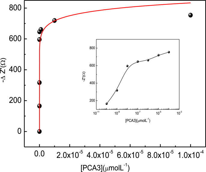
A calibration curve was built from the data in Fig. 4 for the impedance at 30 Hz where one notes in Fig. 5 a sharp increase at low PCA3 concentrations before stabilizing when the active sites available for hybridization tend to zero. This curve can be taken as an adsorption isotherm, and has been fitted with the composition of two Freundlich isotherms. The limit of detection was 83 pM, being therefore more sensitive than using cyclic voltammetry (above) and in a recent work where chitosan and carbon nanotubes were utilized as immobilization matrix, for which the detection limit was 128 pM [22]. The control experiments with electrochemical impedance measurements in Fig. S6 in the Supporting Information (see also the visualization below) indicate no significant changes in impedance when the genosensors were exposed to different concentrations of the non-complementary sequence.
Fig. 5.
Impedance at 30 Hz versus PCA3 concentration from the data in Fig. 4. The curve was fitted using a combination of Freundlich functions. The inset shows the curve fitted in the logarithmic scale. Detection was performed at room temperature of 23 °C.
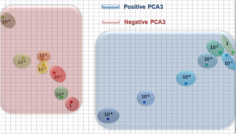
The high sensitivity and selectivity of the genosensor is further confirmed by plotting the impedance data using the multidimensional projection technique IDMAP, as shown in Fig. 6 . A clear distinction can be made of the samples containing the various PCA3 concentrations with the data points referring to the highest concentrations clustering together as saturations is reached. Also these positive controls (in blue) are located on an entirely different space to that of the negative controls corresponding to measurements with different concentrations of the non-complementary sequence (in pink).
Fig. 6.
IDMAP plot for the impedance spectra for different concentrations of: PCA3 complementary sequence. non-complementary sequence. Each point corresponds to an impedance spectrum obtained with the genosensor. Note that the axes are not labeled because in IDMAP plots what matters is the relative distance between projected data points.
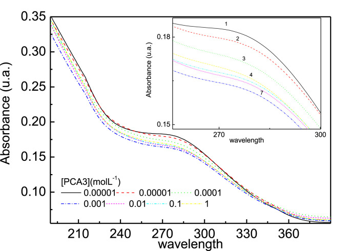
The genosensors could also detect PCA3 using UV–vis. spectroscopy. Film growth on a quartz plate was monitored by measuring the spectrum after depositing each AuNP-CS/Probe bilayer. The spectra in Fig. S3 in the Supporting Information feature a band at 550 nm for gold nanoparticles, which increases with deposition of additional layers up to the 5th layer, as seen in the inset of the figure. Based on these results, the genosensors were made with 5 AuNP-CS/Probe bilayers deposited on quartz. Fig. 7 shows the absorption spectra for the genosensors exposed to different PCA3 concentrations. The band at 260 nm is assigned to absorption of DNA bases of the PCA3 probe and its intensity decreases with increasing PCA3 concentration [41]. This decrease is due to the so-called hypochromic effect [42], explained as follows. The close interaction between stacked bases in nucleic acids causes a decrease in UV light absorption compared to that the absorption of a solution with the same concentration of free nucleotides. It is worth mentioning that this hypochromic effect does not occur when the genosensor is exposed to the non-complementary sequence, as seen in Fig. S7 in the Supporting Information.
Fig. 7.
Absorbance spectra for genosensors made 5-bilayer AuNP-CS/Probe films deposited onto quartz exposed to various concentrations of PCA3 in PBS solutions.
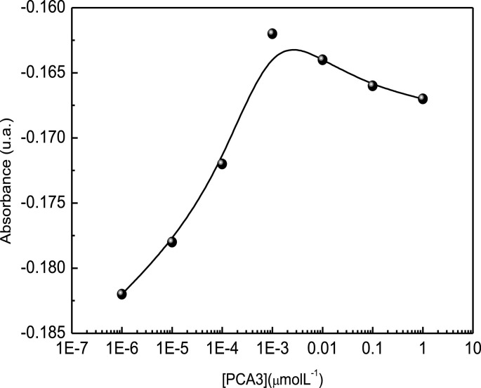
Note in Fig. 8 that the absorbance decreased up to 10−3 μM showing a small increase for higher concentrations. This is consistent with the electrochemical impedance measurements which presented saturation from the same concentration, indicating there were no more free probes at higher concentrations. For this technique the detection limit calculated according to IUPAC recommendation was 900 pM. For better visualization the x axis in Fig. 7 was multiplied by (−1). For UV–vis detection no isotherm fitted the calibration curve owing to the decrease in absorbance at high concentrations.
Fig. 8.
Change in the relative area below the 260 nm band versus PCA3 concentration.
All the techniques employed here for PCA3 gene detection were successful, with electrochemical impedance being the most sensitive with the lowest detection limit. The sensitivity even with the most efficient method is not as high as the one obtained by Fu and colleagues [20] who employed surface-enhanced Raman scattering (SERS) with a device using a PCA3 mimic. The genosensor developed here is nevertheless attractive because it has the advantage of ease of production with low cost; in addition, no sophisticated equipment is required unlike the more sensitive SERS sensor [20]. In future studies the genosensor will be applied to urine samples from patients.
3.2. Diagnosis with image analysis employing machine learning
One of the easiest ways to obtain a fast diagnostic with present technology is to take a picture of a sensing unit exposed to the sample and process the image. This is different from the standard approaches involving image analysis for diagnostics because the image is taken not from the biological sample itself but of the sensing unit. Hence, this strategy will only work if the detection procedure leads to a change in texture or morphology or any other image feature of the sensing units. Since it is well established that the surfaces of biosensors are altered during the measurements, it seems natural to assume that such changes could be utilized for diagnosis. Yet, this strategy has not been explored in the literature. To the best of our knowledge the only work based on image analysis of sensing units is our own [29] in which we proved that the standard deviation of the circularity of objects on SEM images correlated with the concentration of a cancer biomarker. We have therefore decided to extend this research and apply machine learning to the images of genosensors subjected to the same procedures as in the electrochemical and optical detection in the previous subsection.
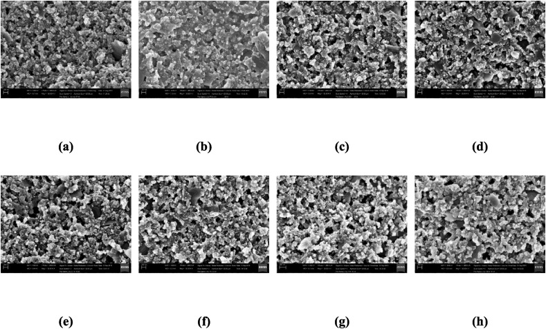
A typical set of representative images are illustrated in Fig. 9 . We used SEM images for proof-of-concepts experiments, though we know ideally one should use optical images. For if the strategy does not work with SEM images that are expected to capture the nanoscopic changes owing to hybridization in the genosensors, it is unlikely that it would work with optical images. The classification was performed in 3 datasets, which differs in number of examples (Table S2) according to the window sizes of the segmentation. The best results for both binary and multiclass classification shown in Table 2 were obtained using the dataset with the windows size of 300 × 300 pixels (the results for the two other datasets are given in Tables S4 and S5). In the table, the accuracy and standard deviation (in parenthesis) for each combination of texture analysis technique and classifier are reported. We used the classifiers Support Vector Machine (SVM) (linear kernel), Linear Discriminant Analysis (LDA) [43] and 1-Nearest Neighborhood (1-NN). The maximum accuracy was 99.9 (0.3) using the LCFNN descriptor with SVM and LDA classifiers in the binary classification. In this procedure, the classification system had the task to distinguish the images of sensing units exposed to PCA3 (with all concentrations put together) from those which were not (negative and blank). Thus, the accuracy indicates a strong ability to separate the two classes.
Fig. 9.
Examples of SEM imagens of the sensor unity with (a) negative sequence, (b) blank and PCA3 biomarker with concentrations (μmol L−1) in increasing order (left-right): (c) 10−5, (d) 10−4, (e) 10−3, (f) 10−2, (g) 10−1, (h) 1.
Table 2.
Accuracy in binary and multiclass classifications for the dataset with window size of 300 × 300 pixels.
| Texture Techniques |
Binary |
Multiclass |
||||
|---|---|---|---|---|---|---|
| Classifier | LDA | SVM | 1-NN | LDA | SVM | 1-NN |
| GLDM | 92.8 (6.7) | 98.7 (1.3) | 98.5 (1.3) | 75.7 (4.4) | 79.3 (3.3) | 62.8 (3.8) |
| Fourier | 92.4 (5.5) | 97.1 (1.9) | 98.6 (1.2) | 56.3 (5.7) | 75.9 (3.9) | 67.2 (5.2) |
| CNTD | 98.1 (1.8) | 96.9 (1.9) | 97.3 (2.0) | 68.6 (5.3) | 75.5 (3.4) | 62.6 (4.1) |
| Fractal | 92.9 (5.8) | 97.9 (1.5) | 96.3 (2.9) | 59.5 (5.2) | 64.2 (4.0) | 52.7 (4.8) |
| AHP | 98.9 (1.3) | 98.8 (1.3) | 98.4 (1.3) | 66.7 (6.2) | 78.2 (3.7) | 68.4 (4.9) |
| LBP | 99.0 (1.3) | 98.6 (1.4) | 94.6 (3.3) | 76.5 (4.7) | 74.7 (3.5) | 72.5 (4.7) |
| CNRNN | 98.1 (1.7) | 98.9 (1.0) | 98.9 (1.0) | 72.7 (4.3) | 82.4 (3.5) | 70.4 (3.7) |
| LCFNN | 99.9 (0.3) | 99.9 (0.3) | 99.5 (0.9) | 88.3 (3.4) | 86.9 (3.1) | 80.3 (3.8) |
When a multiclass classification was attempted, the accuracies decreased because a visual inspection of the images indicates that the changes are small for low PCA3 concentrations. The most efficient combination of texture technique and classifier was based on the LCFNN descriptor and LDA algorithm with an accuracy of 88.3% (3.4). The table also shows that overall the SVM and LDA classifiers combined with LCFNN, CNRNN, and GLDM texture techniques are the most appropriate to separate the groups. The details of all the image processing and the results for all the algorithms and classification conditions are given in the Supporting Information.
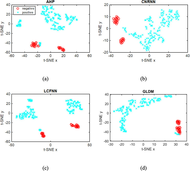
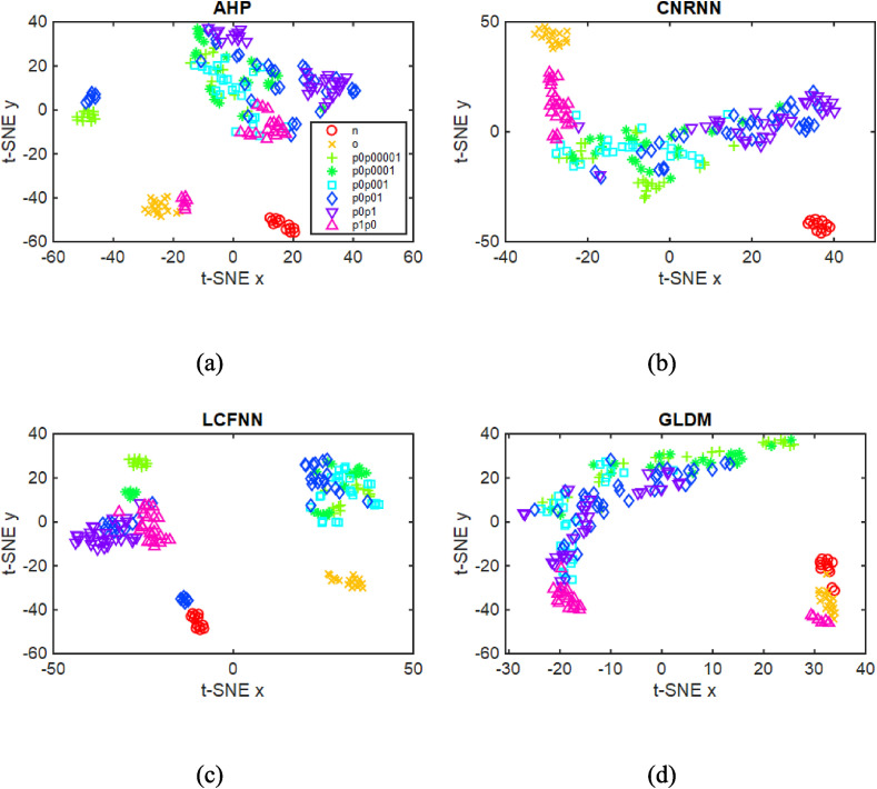
We are aware of the possible overfitting in the analysis with supervised machine learning when the number of images is small, as in our case. We have then also performed a non-supervised data analysis over the image features using the t-Distributed Stochastic Neighbor Embedding (t-SNE) [44], which should be entirely free from overfitting artifacts. This technique is used for high-dimensional data visualization because of its ability to reveal the data structure, such as clusters of similar samples. The same feature vectors employed above were now embedded in a two-dimensional space with t-SNE, which does not require class information. Fig. 10 shows the feature projections of the four best texture descriptors, with the samples (points) labeled using the binary class case only for visualization purposes. This experiment reveals a data structure for the GLDM descriptors that form two main clusters, one comprising the positive (in blue) samples while the other had a majority of negative (in red) samples. The other descriptors also show a clustering structure in which the positive and negative samples can be easily separated, corroborating the results of the binary supervised experiment (Table 2). The projections for the texture features with samples colored using multiclass labels are shown in Fig. 11 , where a cluster is noted for the negative (‘n’ and ‘o’) and ‘p1p0’ classes. The clustering of the other positive classes is less clear, as one should expect from the results of the supervised learning experiment. The accuracy values in Table 3 obtained with K-means are smaller than those in Table 2, with a maximum of 70.83% for the multiclass scenario. This is indeed a more challenging task, which requires more sophisticated and complex image analysis techniques.
Fig. 10.
t-SNE projection of the features for AHP, CRNNN, LCFNN, and GLDM descriptors with the points labeled using the binary class case.
Fig. 11.
t-SNE projection of the features for the AHP, CRNNN, LCFNN, and GLDM descriptors with the points colored using the multiclass label.
Table 3.
Accuracy for the clustering groups computed with k-means in binary and multiclass cases on the dataset with window size of 300 × 300 pixels.
| Texture Techniques | Accuracy (%) |
|
|---|---|---|
| Binary | Multiclass | |
| GLDM | 86.98 | 52.10 |
| Fourier | 87.50 | 62.50 |
| CNTD | 84.37 | 52.60 |
| Fractal | 90.10 | 48.44 |
| AHP | 80.21 | 46.35 |
| LBP | 82.81 | 51.56 |
| CNRNN | 95.83 | 52.10 |
| LCFNN | 87.50 | 70.83 |
The results from the analysis of SEM images of the genosensing units amount to a demonstration that image processing may be a powerful option to complement electrical, electrochemical and optical principles of detection. Nevertheless, the accuracy in discriminating all of the PCA3 concentrations used in the experiments was at most 88.3% for supervised learning and 70.83% for non-supervised learning, while with the electrochemical and optical methods full distinction could be reached. Hence, in further studies we shall explore different image analysis techniques to improve the accuracy in the multiclass scenario, including Convolutional Neural Networks (CNN) [45].
4. Conclusions
We designed a genosensor made with LbL films coated with a layer of a PCA3 probe which proved effective in detecting PCA3 with different principles of detection. The most effective was electrochemical impedance spectroscopy, with which a limit of detection of 83 pM was reached, being more sensitive than the genosensor from our previous work22 probably owing to the incorporation of gold nanoparticles in the LbL film. Using the multidimensional projection technique IDMAP we demonstrate that full distinction of all PCA3 concentrations can be achieved. The high sensitivity and selectivity is related to hybridization, which is very specific, confirmed with PM-IRRAS. The second most efficient method was UV–Vis. spectroscopy, and this is particularly significant because one may now envisage the development of colorimetric tests.
The PCA3 concentration dependence of the electrochemical measurements could be explained with Freundlich and Langmuir-Freundlich models as if hybridization could be simulated as an adsorption process. This specific interaction did affect the morphology of the genosensors when exposed to different PCA3 concentrations or in control experiments, and this allowed us for the first time attempt to detect a cancer biomarker via machine learning of SEM images of the genosensors. The results are encouraging since almost full distinction could be reached for a binary classification for samples with and without PCA3. On the other hand, the distinguishing ability in the multiclass case can still be improved if compared to the other methods (with electrochemical and optical measurements). We should also mention the limitations of our use of machine learning, stemming from the small number of images per condition and the need to employ data augmentation. These issues should be addressed in the future to confirm that no overtraining of data occurs. One may be optimistic nevertheless for further studies including different image analysis techniques since it has already been proven that image contents are correlated with biomarker concentration29.
Taken together, we believe that the results and concepts reported here may pave the way for a new era of diagnostics – not only for prostate cancer – where simple detection methods may be employed which can be leveraged with machine learning of images of the sensing units themselves.
Author contributions
Valquiria C. Rodrigues - performed experiments and prepared the figures, and wrote the manuscript. Juliana C. Soares - carried out the UV–vis spectroscopy measurements and analyzed the corresponding data. Andrey C. Soares - performed the PM-IRRAS measurements and analyzed the spectra. Daniel C. Braz - development of the pipeline and tests of the machine learning algorithms applied to the images. Matias Eliseo Melendez - performed the extraction and preparation of the cell samples and measured the biomarker concentration using electrochemiluminescence at the Barretos Cancer Hospital. Lucas C. Ribas - development of the pipeline and tests of the machine learning algorithms applied to the images. Leonardo F. S. Scabini - development of the pipeline and tests of the machine learning algorithms applied to the images. Odemir M. Bruno - supervision of the experiments using machine learning applied to images. Andre Lopes Carvalho - was responsible for the experiments and data analysis at the Barretos Cancer Hospital. Rui Manuel Reis - was responsible for the experiments and data analysis at the Barretos Cancer Hospital. Rafaela Cristina Sanfelice - responsible for the synthesis of nanoparticles. Osvaldo N. Oliveira Jr - was the coordinator of the research and edited the manuscript.
Declaration of competing interest
The authors declare that they have no known competing financialinterestsor personal relationships that could have appeared to influence the work reported in this paper.
Acknowledgements
This work was supported by Coordination of Superior Level Staff Improvement ( CAPES, Brazil) (88887.364257/2019–00), National Council for Scientific and Technological Development ( CNPq, Brazil) and São Paulo Research Foundation (FAPESP, Brazil) (2016/23763–8, 2018/18953–8, 2018/22214–6, 2019/07811–0). Daniel C. Braz thanks the Mato Grosso do Sul State University (Dourados, MS, Brazil) for the training program.
Footnotes
Supplementary data to this article can be found online at https://doi.org/10.1016/j.talanta.2020.121444.
Appendix A. Supplementary data
The following is the Supplementary data to this article:
References
- 1.Bhatt G., Bhattacharya S. Biosensors on chip: a critical review from an aspect of micro/nanoscales. J. Micromanufacturing. 2019;2:198–219. doi: 10.1177/2516598419847913. [DOI] [Google Scholar]
- 2.Qian L., Li Q., Baryeh K., Qiu W., Li K., Zhang J., Yu Q., Xu D., Liu W., Brand R.E., Zhang X., Chen W., Liu G. Biosensors for early diagnosis of pancreatic cancer: a review. Transl. Res. 2019;213:67–89. doi: 10.1016/j.trsl.2019.08.002. [DOI] [PubMed] [Google Scholar]
- 3.Liu J., Jasim I., Shen Z., Zhao L., Dweik M., Zhang S., Almasri M. A microfluidic based biosensor for rapid detection of Salmonella in food products. PloS One. 2019;14 doi: 10.1371/journal.pone.0216873. [DOI] [PMC free article] [PubMed] [Google Scholar]
- 4.Kassal P., Steinberg M.D., Steinberg I.M. Wireless chemical sensors and biosensors: a review. Sensor. Actuator. B Chem. 2018;266:228–245. doi: 10.1016/j.snb.2018.03.074. [DOI] [Google Scholar]
- 5.Goldsmith B.R., Locascio L., Gao Y., Lerner M., Walker A., Lerner J., Kyaw J., Shue A., Afsahi S., Pan D., Nokes J., Barron F. Digital biosensing by foundry-fabricated graphene sensors. Sci. Rep. 2019;9 doi: 10.1038/s41598-019-38700-w. [DOI] [PMC free article] [PubMed] [Google Scholar]
- 6.Ibau C., Md Arshad M.K., Gopinath S.C.B. Current advances and future visions on bioelectronic immunosensing for prostate-specific antigen. Biosens. Bioelectron. 2017;98:267–284. doi: 10.1016/j.bios.2017.06.049. [DOI] [PubMed] [Google Scholar]
- 7.Zadra G., Priolo C., Patnaik A., Loda M. New strategies in prostate cancer: targeting lipogenic pathways and the energy sensor AMPK. Clin. Canc. Res. 2010;16:3322–3328. doi: 10.1158/1078-0432.CCR-09-1955. [DOI] [PMC free article] [PubMed] [Google Scholar]
- 8.Nogueira L., Corradi R., Eastham J.A. Prostatic specific antigen for prostate cancer detection. Int. Braz J. Urol. 2009;35:521–531. doi: 10.1590/S1677-55382009000500003. [DOI] [PubMed] [Google Scholar]
- 9.Day J.R., Jost M., Reynolds M.A., Groskopf J., Rittenhouse H. PCA3: from basic molecular science to the clinical lab. Canc. Lett. 2011;301:1–6. doi: 10.1016/j.canlet.2010.10.019. [DOI] [PubMed] [Google Scholar]
- 10.Pepe P., Fraggetta F., Galia A., Skonieczny G., Aragona F. PCA3 score and prostate cancer diagnosis at repeated saturation biopsy. Which cut-off: 20 or 35? Int. Braz J. Urol. 2012;38:489–495. doi: 10.1590/S1677-55382012000400008. [DOI] [PubMed] [Google Scholar]
- 11.Marks L.S., Fradet Y., Lim Deras I., Blase A., Mathis J., Aubin S.M.J., Cancio A.T., Desaulniers M., Ellis W.J., Rittenhouse H., Groskopf J. PCA3 molecular urine assay for prostate cancer in men undergoing repeat biopsy. Urology. 2007;69:532–535. doi: 10.1016/j.urology.2006.12.014. [DOI] [PubMed] [Google Scholar]
- 12.Rastogi V., Yadav P., Bhattacharya S.S., Mishra A.K., Verma N., Verma A., Pandit J.K. Carbon nanotubes: an emerging drug carrier for targeting cancer cells. J. Drug Deliv. 2014:1–23. doi: 10.1155/2014/670815. [DOI] [PMC free article] [PubMed] [Google Scholar]
- 13.Neves A.F., Dias-Oliveira J.D.D., Araújo T.G., Marangoni K., Goulart L.R. Prostate cancer antigen 3 (PCA3) RNA detection in blood and tissue samples for prostate cancer diagnosis. Clin. Chem. Lab. Med. 2013;51 doi: 10.1515/cclm-2012-0392. [DOI] [PubMed] [Google Scholar]
- 14.Pasinszki T., Krebsz M., Tung T.T., Losic D. Carbon nanomaterial based biosensors for non-invasive detection of cancer and disease biomarkers for clinical diagnosis. Sensors. 2017;17:1919. doi: 10.3390/s17081919. [DOI] [PMC free article] [PubMed] [Google Scholar]
- 15.Vilela P., El-Sagheer A., Millar T.M., Brown T., Muskens O.L., Kanaras A.G. Graphene oxide-upconversion nanoparticle based optical sensors for targeted detection of mRNA biomarkers present in alzheimer's disease and prostate cancer. ACS Sens. 2017;2:52–56. doi: 10.1021/acssensors.6b00651. [DOI] [PubMed] [Google Scholar]
- 16.Bourdoumis A., Papatsoris A.G., Chrisofos M., Efstathiou E., Skolarikos A., Deliveliotis C. The novel prostate cancer antigen 3 (PCA3) biomarker. Int. Braz J. Urol. 2010;36:665–669. doi: 10.1590/S1677-55382010000600003. [DOI] [PubMed] [Google Scholar]
- 17.Shen M., Chen W., Yu K., Chen Z., Zhou W., Lin X., Weng Z., Li C., Wu X., Tao Z. The diagnostic value of PCA3 gene-based analysis of urine sediments after digital rectal examination for prostate cancer in a Chinese population. Exp. Mol. Pathol. 2011;90:97–100. doi: 10.1016/j.yexmp.2010.10.009. [DOI] [PubMed] [Google Scholar]
- 18.McKillop C. Interview with jack schalken. Eur. Urol. 2006;50:153–154. doi: 10.1016/j.eururo.2006.04.021. [DOI] [PubMed] [Google Scholar]
- 19.Hessels D., Schalken J.A. The use of PCA3 in the diagnosis of prostate cancer. Nat. Rev. Urol. 2009;6:255–261. doi: 10.1038/nrurol.2009.40. [DOI] [PubMed] [Google Scholar]
- 20.Fu X., Wen J., Li J., Lin H., Liu Y., Zhuang X., Tian C., Chen L. Highly sensitive detection of prostate cancer specific PCA3 mimic DNA using SERS-based competitive lateral flow assay. Nanoscale. 2019;11:15530–15536. doi: 10.1039/C9NR04864B. [DOI] [PubMed] [Google Scholar]
- 21.Eskra J.N., Rabizadeh D., Pavlovich C.P., Catalona W.J., Luo J. Approaches to urinary detection of prostate cancer. Prostate Cancer Prostatic Dis. 2019;22:362–381. doi: 10.1038/s41391-019-0127-4. [DOI] [PMC free article] [PubMed] [Google Scholar]
- 22.Soares J.C., Soares A.C., Rodrigues V.C., Melendez M.E., Santos A.C., Faria E.F., Reis R.M., Carvalho A.L., Oliveira O.N., Jr. Detection of the prostate cancer biomarker PCA3 with electrochemical and impedance-based biosensors. ACS Appl. Mater. Interfaces. 2019 doi: 10.1021/acsami.9b19180. acsami.9b19180. [DOI] [PubMed] [Google Scholar]
- 23.Chistiakov D.A., Myasoedova V.A., Grechko A.V., Melnichenko A.A., Orekhov A.N. New biomarkers for diagnosis and prognosis of localized prostate cancer. Semin. Canc. Biol. 2018;52:9–16. doi: 10.1016/j.semcancer.2018.01.012. [DOI] [PubMed] [Google Scholar]
- 24.Decher G. Fuzzy nanoassemblies: toward layered polymeric multicomposites. Science. 1997;277:1232–1237. doi: 10.1126/science.277.5330.1232. [DOI] [Google Scholar]
- 25.Hang J., Shi L., Feng X., Xiao L. Electrostatic and electrosteric stabilization of aqueous suspensions of barite nanoparticles. Powder Technol. 2009;192:166–170. doi: 10.1016/j.powtec.2008.12.010. [DOI] [Google Scholar]
- 26.Melo M.A., Jr., Santos L.S.S., Gonçalves M. do C., Nogueira A.F. Preparação de nanopartículas de prata e ouro: um método simples para a introdução da nanociência em laboratório de ensino. Quím. Nova. 2012;35:1872–1878. doi: 10.1590/S0100-40422012000900030. [DOI] [Google Scholar]
- 27.Paulovich F.V., Moraes M.L., Maki R.M., Ferreira M., Oliveira O.N., Jr., de Oliveira M.C.F. Information visualization techniques for sensing and biosensing. The Analyst. 2011;136:1344. doi: 10.1039/c0an00822b. [DOI] [PubMed] [Google Scholar]
- 28.Rodrigues V.C., Moraes M.L., Soares J.C., Soares A.C., Sanfelice R., Deffune E., Oliveira O.N., Jr. Immunosensors made with layer-by-layer films on chitosan/gold nanoparticle matrices to detect D-dimer as biomarker for venous thromboembolism. Bull. Chem. Soc. Jpn. 2018 doi: 10.1246/bcsj.20180019. [DOI] [Google Scholar]
- 29.Rodrigues V. da C., Comin C.H., Soares J.C., Soares A.C., Melendez M.E., Fregnani J.H.T.G., Carvalho A.L., Costa L. da F., Oliveira O.N., Jr. Analysis of scanning electron microscopy images to investigate adsorption processes responsible for detection of cancer biomarkers. ACS Appl. Mater. Interfaces. 2017;9:5885–5890. doi: 10.1021/acsami.6b16105. [DOI] [PubMed] [Google Scholar]
- 30.Humeau-Heurtier A. Texture feature extraction methods: a survey. IEEE Access. 2019;7:8975–9000. doi: 10.1109/ACCESS.2018.2890743. [DOI] [Google Scholar]
- 31.Weszka J.S., Dyer C.R., Rosenfeld A. A comparative study of texture measures for terrain classification. IEEE Trans. Syst. Man Cybern SMC- 1976;6:269–285. doi: 10.1109/TSMC.1976.5408777. [DOI] [Google Scholar]
- 32.Journaux L., Destain M.-F., Miteran J., Piron A., Cointault F. In: Artif. Neural Netw. Pattern Recognit. Prevost L., Marinai S., Schwenker F., editors. Springer Berlin Heidelberg; Berlin, Heidelberg: 2008. Texture classification with generalized fourier descriptors in dimensionality reduction context: an overview exploration; pp. 280–291.http://link.springer.com/10.1007/978-3-540-69939-2_27 [Google Scholar]
- 33.Backes A.R., Casanova D., Bruno O.M. Texture analysis and classification: a complex network-based approach. Inf. Sci. 2013;219:168–180. doi: 10.1016/j.ins.2012.07.003. [DOI] [Google Scholar]
- 34.Backes A.R., Casanova D., Bruno O.M. Plant leaf identification based on volumetric fractal dimension. Int. J. Pattern Recogn. Artif. Intell. 2009;23:1145–1160. doi: 10.1142/S0218001409007508. [DOI] [Google Scholar]
- 35.Zhu Z., You X., Chen C.L.P., Tao D., Ou W., Jiang X., Zou J. An adaptive hybrid pattern for noise-robust texture analysis. Pattern Recogn. 2015;48:2592–2608. doi: 10.1016/j.patcog.2015.01.001. [DOI] [Google Scholar]
- 36.Ojala T., Pietikainen M., Maenpaa T. Multiresolution gray-scale and rotation invariant texture classification with local binary patterns. IEEE Trans. Pattern Anal. Mach. Intell. 2002;24:971–987. doi: 10.1109/TPAMI.2002.1017623. [DOI] [Google Scholar]
- 37.Ribas L.C., Sá Junior J.J. de M., Scabini L.F.S., Bruno O.M. Fusion of complex networks and randomized neural networks for texture analysis. Pattern Recogn. 2020;103:107189. doi: 10.1016/j.patcog.2019.107189. [DOI] [Google Scholar]
- 38.Więckowski A., Korzeniewski C., Braunschweig B., editors. Vibrational Spectroscopy at Electrified Interfaces. Wiley; Hoboken, New Jersey: 2013. [Google Scholar]
- 39.Colthup N.B., Daly L.H., Wiberley S.E. third ed. Academic Press; Boston: 1990. Introduction to Infrared and Raman Spectroscopy. [Google Scholar]
- 40.Soares A.C., Soares J.C., Rodrigues V.C., Follmann H.D.M., Arantes L.M.R.B., Carvalho A.C., Melendez M.E., Fregnani J.H.T.G., Reis R.M., Carvalho A.L., Oliveira O.N., Jr. Microfluidic-based genosensor to detect human papillomavirus (HPV16) for head and neck cancer. ACS Appl. Mater. Interfaces. 2018;10:36757–36763. doi: 10.1021/acsami.8b14632. [DOI] [PubMed] [Google Scholar]
- 41.Voet D., Voet J.G. second ed. J. Wiley & Sons; New York: 1995. Biochemistry. [Google Scholar]
- 42.Lehninger A.L., Nelson D.L., Cox M.M. sixth ed. W.H. Freeman; New York: 2013. Lehninger Principles of Biochemistry. [Google Scholar]
- 43.Webb A.R. second ed. Wiley; West Sussex, England ; New Jersey: 2002. Statistical Pattern Recognition. [Google Scholar]
- 44.Maaten L.V.D., Hinton G. Visualizing data using t-SNE. J. Mach. Learn. Res. 2008;9:2579–2605. [Google Scholar]
- 45.Liu W., Wang Z., Liu X., Zeng N., Liu Y., Alsaadi F.E. A survey of deep neural network architectures and their applications. Neurocomputing. 2017;234:11–26. doi: 10.1016/j.neucom.2016.12.038. [DOI] [Google Scholar]
Associated Data
This section collects any data citations, data availability statements, or supplementary materials included in this article.


