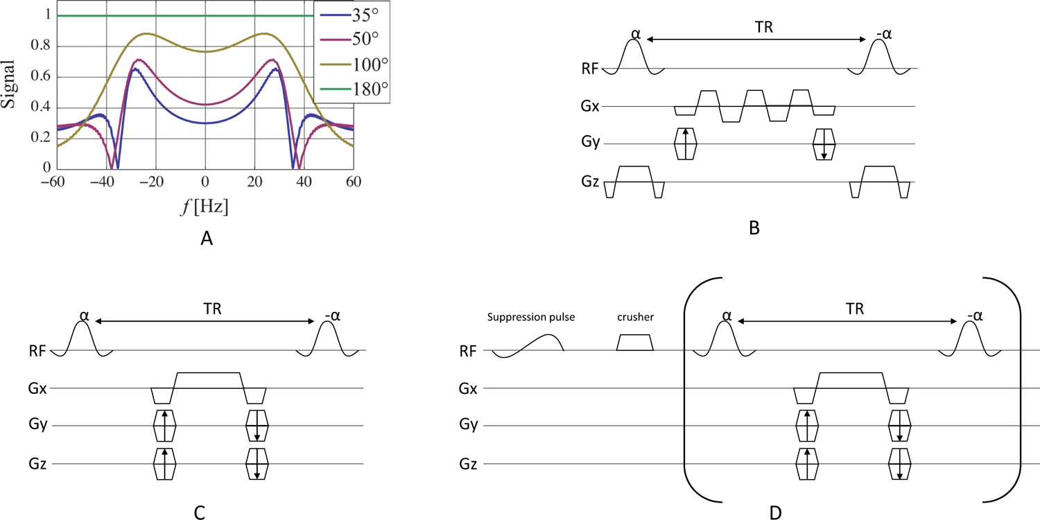
Figure 9:

Simulated SSFP signal as a function of frequency and flip angle for TR = 14.3 ms (A). The choice of flip angle in the bSSFP sequence is a tradeoff between alleviating banding artifacts with high flip angles and preserving magnetization for dynamic imaging with lower flip angles. Pulse sequence diagrams for bSSFP, including (B) multi-echo readouts to decompose spectral information, (C) metabolite specific acquisition, and (D) metabolite specific acquisition with spectral suppression of undesired signal at the beginning of the acquisition. Portions of this figure are adapted from Ref. (73).
