Abstract
Currently, the “2019-CoV-2” has been raging across the world for months, causing massive death, huge panic, chaos, and immeasurable economic loss. Such emerging epidemic viruses come again and again over years, leading to similar destructive consequences. Air-borne transmission among humans is the main reason for the rapid spreading of the virus. Blocking the air-borne transmission should be a significant measure to suppress the spreading of the pandemic. Considering the hospital is the most probable place to occur massive cross-infection among patients as emerging virus usually comes in a disguised way, an air distribution optimization of a general three-bed hospital ward in China is carried out in this paper. Using the Eulerian-Lagrangian method, sneeze process from patients who are assumed to be the virus carrier, which is responsible for a common event to trigger cross-infection, is simulated. The trajectory of the released toxic particle and the probability of approaching others in the same ward are calculated. Two evaluation parameter, total maximum time (TMT) and overall particle concentration (OPC) to reflect the particle mobility and probability to cause cross-infection respectively, are developed to evaluate the proposed ten air distributions in this paper. A relatively optimized air distribution proposal with the lowest TMT and OPC is distinguished through a three-stage analysis. Results show that a bottom-in and top-out air distribution proposal is recommended to minimize cross-infections.
Keywords: Coronavirus, Air distribution, Cross infection, Computational fluid flow, Discrete phase model
Highlights
-
•
A ward-based sneeze process from a patient with epidemic disease is modelled.
-
•
Air distribution (AD) affects the flow pattern of the sneeze-induced virus particles.
-
•
Ten AD proposals are developed to evaluate the their probability of cross-infection.
-
•
Two parameters are proposed to judge which proposals is better quantitatively.
-
•
The direct probability of cross-infection can be decreased by 95% via optimization.
Nomenclature
Local sound velocity (m/s)
Model coefficient
Specific heat of the air (J/kg)
Drag force coefficient
Diameter of the particle (m)
- g
Gravitational acceleration (m/s2)
Turbulent kinetic energy (J)
Mass variance in a controlled volume (kg)
Initial mass of a virus particle (kg)
Mass flow rate of the target particle (kg/s)
Mass flow rate of the particle (kg/s)
Average mass of the particle in a controlled volume (kg)
- p
Pressure (Pa)
Relative Reynold number
Universal internal source term
Universal external source term
Time step size (s)
- T
Temperature (K)
Temperature variance (K)
Velocity components in the x axis (m/s)
Velocity vector (m/s)
- V
Velocity components in the y axis (m/s)
Velocity perpendicular to the gravity (m/s)
Velocity components in the z axis (m/s)
Greek symbols
Coefficient of thermal expansion of the air (1/K)
Dissipation rate of the turbulent energy
Universal variable
Dynamic viscosity of the air (N s/m2)
Turbulent viscosity (N s/m2)
Density of the air (kg/m3)
- λ
Heat transfer coefficient (W m−2K −1)
Mean free path of gas molecules (m)
Universal transport coefficient
Subscripts
Particle
1. Introduction
Recently, a novel coronavirus named “2019-CoV-2” has caused a huge outbreak of atypical pneumonia in Wuhan, Hubei, China (Zhu et al., 2020). During months, tens of thousands of human infections have been confirmed in China and even more confirmed (up to millions) cases have been reported across the world rapidly (Wang et al., 2020c). Efficient human-human transmission should be mainly responsible for such rapid infection of the pandemic. Several specific approaches of the transmission of the virus such as droplet transmission (Handbook of prevention and treatment, 2020), close contact (Li et al., 2020b), and possibly, aerosol transmission (Perlman, 2020) have been identified by scientists, which means that the air-borne transmission, where viruses can be transmitted among humans through aerosol or droplet particles diffused in the air way, can be confirmed to be the primary means to cause human-human transmissions. Similarly, air-borne transmission is also one of the main transmission means for the Middle-East Respiratory Syndrome-associated coronavirus (MERS-CoV) (Kim et al., 2016), Ebola virus (Osterholm et al., 2015), and SARS virus (2003) (Ignatius et al., 2004), which are all deadly viruses causing large population infections globally. Such emerging and re-emerging pathogens challenge public health across the world over years, causing panic and economic loss. How can human actively control the disease transmission from the very beginning when these viruses initially come to host human cells without spotlight should be the key to prevent large-scale global transmission of the epidemic. Blocking air-borne transmission path would be the key to the key.
As numerous target virus cells can be found in the patient’s air way, coughs and sneezes, which was called “violent respiratory events” by Dr. Bourouiba et al. (2014), play a key role in transferring such epidemic viruses that causes respiratory diseases between human and human especially in a hospital. As shown in Fig. 1 , considerable droplets with a certain initial velocity are generated during a human sneeze. These droplets can travel as far as 7–8 m and many can suspend in the air for minutes (Bourouiba, 2020) because of the entrainment effect of the sneeze-induced turbulence (Scharfman et al., 2016). It can be inferred that sneezes or coughs from a patient who is carrying a certain emerging virus sneezes will increase the probability to transfer this virus to others around as these ejected droplets containconsiderable such viruses. Such public-health-threatening events may occur frequently in the hospital. It is even more dangerous when the virus transmission is in its early phase as neither active safety precautions would put in place nor the public would be vigilant enough against such emerging virus. What’s worse, symptoms caused by these emerging virus in the past twenty years such as “Covid-19” and “SARS” are similar to common cold or influenza (Huang et al., 2020) where the patients with the emerging virus are more likely to be mixed with other patients. Therefore, a passive precaution in the hospital for blocking the air-borne transmission of emerging epidemic viruses is critical to prevent cross-infection of patients and a widespread infection in an early stage of a world pandemics.
Fig. 1.

Single high-speed image of Sneeze (Scharfman et al., 2016).
A proper air distribution (AD) is classified into the above-mentioned passive precaution in this paper. Although the air distribution is not a strictly passive measure as the air conditioning system consumes energy, it exists everywhere to protect or harm human under the attack of air-borne virus without human conscious activity once the air conditioning system was installed. As mentioned before, the AD could assist the virus to host in the human cell if it is not arranged properly since the air quality largely depends on the AD (Yu et al., 2017; Chuang et al., 2017). Scientists have paid attention to the indoor AD system concerning the indoor air quality (Verma et al., 2018). Results from previous studies shows that inlet airflow direction (Ganesh et al., 2020), indoor heating sources (Ganesh et al., 2020, Ganesh et al., 2020), and air change rate (ACH) (Verma et al., 2017) could be key factors to influence the air quality indoor. In addition, Verma et al. (2015) found that flow stagnant area in the intensive care unit is the high-risky location which indicates that a proper AD system would minimize the probability of cross-infection. However, there has been no detailed investigation on the AD optimization for minimizing the cross-infection. Considering the AD could determine the flow pattern of the tiny contaminants indoor such as the virus bio-aerosols, it should be a critical factor to control the probability of cross-infection among patients in a same ward which is a relatively confined space. Therefore, the AD optimization within the ward is imperative to be conducted.
AD optimization is a topic of general interests across the world as it is highly related to the indoor air quality and human health. Scientists did an extensive study on the AD in the cabin of the commercial airplane which is also a confined space. As shown in Fig. 2 (a), a AD system where the fresh air flow is supplied from the top and taken away from the bottom was commonly applied to the Boeing and Airbus commercial airplane in the early twenty-first century (Zhang et al., 2017). In 2013, Zhang et al. (2013) developed a novel air displacement where the air flow is supplied from the bottom and taken away from the top whose schematic view is shown in Fig. 2 (b). Results demonstrates that the proposed one can eliminate the contaminants more efficiently than the traditional one. A personalized AD system where the fresh air is supplied from personalized inlets installed in the seats or handrails was proposed by Zhang et al. (2010) The proposed air supply inlet can directly transport the conditional air to the breathing area where the CO2 concentration can be reduced by 30% compared with the traditional AD proposal. Pang et al. (2013) improved the personalized AD system where the air is supplied from the under-floor and seatbacks and is absorbed from the ceiling and bottom of baggage hold. Using laser-based flow visualization technology, the proposed scheme was experimentally proved to be able to overcome stratification of the contaminated air above heads of passengers. From the literature review, it can be concluded that a bottom-in and top-out AD pattern will be better for the indoor air quality.
Fig. 2.
Typical AD systems in a airplane cabin, (a) top-in and bottom-out; (b) bottom-in and top-out (Zhang et al., 2017).
Although more attention has been paid to the AD optimization of commercial aircraft cabins, such investigation on a specific confined ground space especially a hospital ward, as mentioned above, is relatively insufficient. A traditional AD system where the air inlet is arranged in the ceiling is rather common in the civil engineering currently, while it is not recommended for the AD arrangement in an airplane passenger cabin from the literature review above. Facing the severe consequences brought by the widespread epidemic diseases, it is imperative for scientists and engineers to improve the AD inside a general ward to minimize the probability of cross-infection in a hospital ward.
In order to narrow the gap of the understanding of how the AD affects the probability of cross-infection among people in a hospital ward, up to ten AD proposals in a common hospital ward are displayed in this paper. A Eulerian-Lagrangian scheme is adopted to simulate the sneeze process from patients with a specific infectious disease where large amount of virus particle is ejected through patients’ mouths. Such simulating scheme has been successfully utilized in the water spray system (Sun et al., 2018) where numerous fine droplets are sprayed out of a nozzle by pressure (Wang et al., 2015, 2018, 2019), which is similar to a human sneeze. Such method can also be used to track dust particle diffusion movement (Chen et al., 2018). Based on the control-volume-based computational fluid dynamics (CFD) simulation, the authors provided quantitative analyses of each AD proposal to demonstrate which one is the best for minimizing cross-infection. Two critical parameters, which are the total maximum time (TMT) and overall particle concentration (OPC), play a critical part in the AD selection and evaluation. At last, a relatively optimized AD proposal and general air distribution suggestions are offered based on the CFD investigation. The largest novelty in this paper lies in the efforts towards a relatively optimized AD system for minimizing cross-infection in a hospital. In addition, this paper offers these newly-developed two parameters (TMT and OPC), which can give a quantitative evaluation of each AD. These two factors facilitate the selection and identification of an optimized AD arrangement in this paper and future investigations.
Reminders of this paper is organized as follows. Detailed descriptions of the focused ward and proposed ten AD proposals are provided in Section 2. Section 3 describes the CFD simulation relates such as meshing, governing equation, simulation cases, and boundary conditions. Simulation results and discussions are provided in Section 4. Main conclusions are drawn in Section 5.
2. Focused ward structure and AD proposals
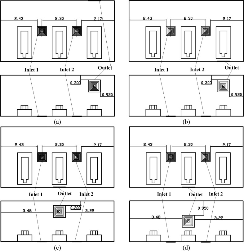
As shown in Fig. 3 , a general three-bed hospital ward in China with three patients is the focus in this paper. The ward’s length × width × height is 7.50 × 4.00 × 2.70 m3. The surface index is also provided in Fig. 3 where the Wall and door, Wall 2, Wall 3, Wall 4, Bed 1, Man 1, Bed 2, Man 2, Bed 3, and Man 3 are clearly marked. The center coordinate (x, y, z) of the mouths of man 1, man 2, and man 3 are (5.92, 0.720, 0.440), (3.62, 0.720, 0.440), and (1.32, 0.720, 0.440). The internal detailed size of the bed, patient, and their relative positions can be seen in Fig. 4 (a). Fig. 4 displays four first-stage AD proposals with two inlets (Inlet 1 and Inlet 2) and one outlet. The size of the inlet is 0.600 × 0.600 m2 and the size of the outlet is 0.800 × 0.800 m2. Fig. 4 (a) displays the Proposal A with two inlets on the ceiling and an outlet on the lower part of the Wall 2. The two inlets of the Proposals B and C are both on the Wall 4 and their inlets on the ceiling. For Proposal B, the outlet is closer to Man 2 and for Proposal C, the outlet is closer to Man 3. The two inlets are on the center line of the Floor in the z direction and the outlet is on the upper part of the Wall 2.
Fig. 3.
Structure and its overall size of a general three-bed hospital ward in China. (Unit: m).
Fig. 4.
Four AD proposals in the first stage, (a) Proposal A; (b) Proposal B; (c) Proposal C; (d) Proposal D. (Unit: m).
Fig. 5 shows the second-stage four proposals in which the two inlets are on the Floor which is the same of that in the Proposal D. The outlet of the Proposal E is on the upper part of the Wall 2. The difference between the D and E is that the outlet of E is closer to Man 3. The outlet of the Proposal F resides on the Wall 4, which is opposite to the outlet in the Proposal E. That means the outlet of the Proposal F is much closer to Man 3, compared with Proposal E. In the Proposals G and H, their outlets are both on the Wall 4 as well. The outlet of the Proposal G is opposite to that of the Proposal D. For Proposal H, the outlet is relatively lower than that of the Proposal G in the y direction.
Fig. 5.
AD proposals in the two-stage, (a) Proposal E; (b) Proposal F; (c) Proposal G(I); (d) Proposal H(J). (Unit: m).
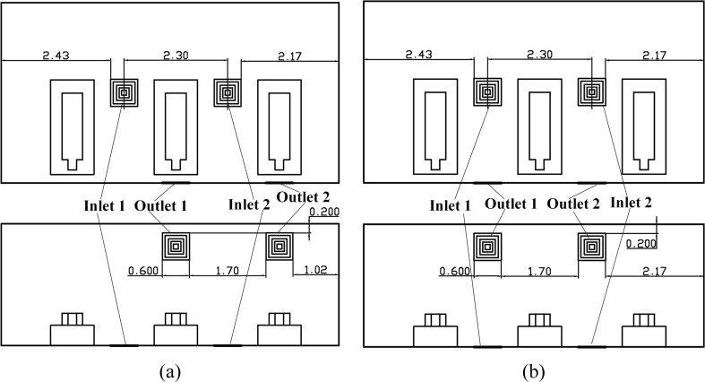
Proposals in the final stage is demonstrated in Fig. 6 . The two inlets in this stage are still resides on the Floor. The number of the outlet is increased to two to gain a better air quality and less possibility to catch cross-infection. These outlets are all on the upper part of the Wall 4. The Proposal I have these two outlets right above Man 2 and Man3 respectively, which is slightly different from the Proposal J as shown in Fig. 6 (b). Note that the size of the outlet is 0.600 × 0.600 m2, which is the same as that of the inlet.
Fig. 6.
Two air distribution proposals in the final stage, (a) Proposal I (H); (b) Proposal J (G). (Unit: m).
3. Mathematical formulation
As shown in Fig. 1, human sneeze is a complicated process as it includes highly unsteady and coupled processes. Such phenomenon contains both continuous and discrete phases, the Eulerian-Lagrangian approach is adopted to describe this multiphase flow (Wang et al., 2020a, Wang et al., 2020b). The surrounding air medium flowing pattern which is primarily influenced by the AD is modelled by Eulerian method, and the movement of discrete ejected virus particles is tracked by the Lagrangian formulation.
3.1. Continuous phase model
The continuous air flow is modelled by the time-averaged N–S equations. The general form of the mass, momentum, and energy conservation can be modelled by Equation (1).
| (1) |
where is the air density. is a universal variable which can represent different variables. , and are the velocity components in the x, y, and z direction. and are the universal transport coefficient and internal source term. is the external source term representing the two-way coupling between the discrete phase and continuous phase. Detailed form of the , , , and are listed in Table 1 where T is the temperature, is the dynamic viscosity of the air, p is the pressure, g is the gravitational acceleration, is the mass variance in a controlled volume, is the initial mass of a virus particle, is the mass flow rate of the target particle, is the drag force coefficient, is the relative Reynold number between the air and particle, is the diameter of the particle, is the mass flow rate of the particle, is the time step size, is the average mass of the particle in a controlled volume.
Table 1.
Detailed form of the , , , and in Equation (1).
| Equation type | ||||
|---|---|---|---|---|
| Mass conservation equation | 1 | 0 | 0 | |
| Momentum conservation equation in the x direction | ||||
| Momentum conservation equation in the y direction | ||||
| Momentum conservation equation in the z direction | ||||
| Energy conservation equation | 0 |
3.2. Turbulence model
Since a human sneeze is a turbulent process (Bourouiba, 2020), a proper turbulence model is demanded. The realizable k-ε model, proposed by Shih et al. (1995), can give an acceptable accuracy with a relatively low computational cost (Pereira et al., 2016). Such method has been applied to various applications such as incompressible turbulent simulation (Silvis et al., 2017), water atomization process (Liu et al., 2018), pollutant particle control (Yin et al., 2019), etc. Therefore, it is adopted in this paper to describe the flow pattern within the ward. The equation for solving the turbulent kinetic energy and dissipation rate are acquired by Equations (2), (3) where is the turbulent viscosity which can be acquired by Equation (4). Values of the coefficient in Equations (2), (3) are listed in Table 2 where is the flow velocity perpendicular to the gravity, and is the turbulent Mach number which can be obtained by Equation (5).
| (2) |
| (3) |
| (4) |
| (5) |
Table 2.
| Coefficient | Calculation formula | Physical meaning |
|---|---|---|
| Turbulence kinetic energy produced by the average velocity gradient. | ||
| Turbulence kinetic energy produced by the buoyancy force. | ||
| Fluctuation effect on the total dissipation rate in compressible flow | ||
| 1 | Model constant | |
| 1.2 | Model constant | |
| Model constant | ||
| Turbulent time scale divided by time-averaged strain rate of the air | ||
| time-averaged strain rate of the air | ||
| 1.9 | Model constant | |
| 1.44 | Model constant | |
| The buoyancy effect on |
3.3. Discrete phase model
The movement of the virus particle, which is the bio-aerosol particle, is governed by the Newton’s second law (Wang et al., 2017). The trajectory of the discrete particle is solved by the differential equation of force loaded upon the particle in the integral Lagrangian coordinate framework (Verma et al., 2017; Dbouk and Drikakis, 2020; Li et al., 2020c). The motion of a single particle in Cartesian coordinate system can be obtained by Equation (6) where is the drag force per unit particle mass per relative velocity, and is additional acceleration force per unit mass except the drag force and gravitational force. Considering the virus particle generated by a human sneeze is between 1 and 10 μm (Yang et al., 2007), Stokes Drag force equation is adopted to calculate the , which is expressed by Equation (7) where the , called Cunningham coefficient, is calculated to be 1 under the atmospheric condition by Equation (8) (Chen and Deng, 2017, Zhang et al., 2013). Also, because of the size of the bio-aerosol particle, the Brownian force and Saffman lift force are considered in the , where the detailed form can be obtained in (Li et al., 1992).
| (6) |
| (7) |
| (8) |
4. Computational model
Numerical study in this paper is accomplished by the software of Ansys-Fluent as similar numerical investigation on the ventilation system (Zhou et al., 2020), indoor pollutant control (Milner et al., 2011), and sprayed droplet flow process (Liu et al., 2018), flow dynamics in power system (Li et al., 2020a) etc. has been successfully carried out by it. In this section, mesh configuration, simulation conditions, boundary conditions, and simulation processes are provided in detail.
4.1. Mesh condition
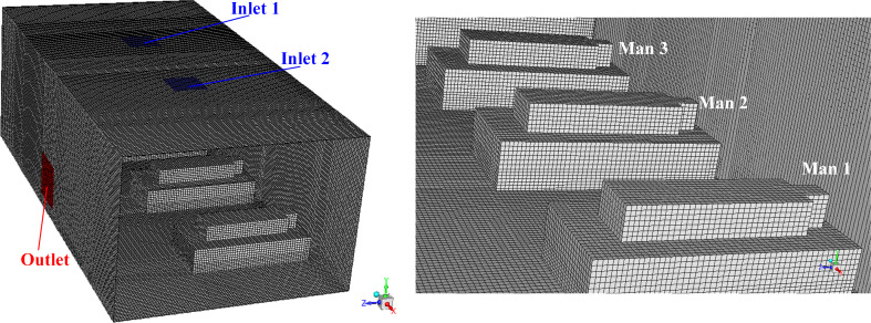
In order to gain a better calculation accuracy, structured mesh and encryption method near the wall is adopted. The generation of the mesh was done by the software ICEM. Although there are ten AD proposals, the overall structure of the computational model is the same. Therefore, taking the Proposal A as an example, the overall structured mesh condition and a close look of the mesh is shown in Fig. 7 . The total mesh number is 748415, the network quality of which are all above 0.9, illustrating a perfect mesh quality (Chen et al., 2018). Results of the mesh sensitivity analysis is provided in Table 3 , in which it shows that the mesh number of 748415 can attain both the accuracy and computational economy.
Fig. 7.
Mesh condition of the computational model, (a) overlook of the mesh condition for the Proposal A; (b) a close look of the structured mesh inside the hospital ward.
Table 3.
Mesh sensitivity analysis of the Proposal A with the center point whose coordinate is (3750, 1350, 2000).
| Mesh number | 224546 | 748415 | 1085941 | 1434653 |
|---|---|---|---|---|
| Velocity magnitude (m/s) | 0.19434 | 0.24331 | 0.24223 | 0.24236 |
| Gauge Pressure (Pa) | 2.9754 | 2.8164 | 2.8163 | 2.8166 |
4.2. Simulation conditions, cases, solution, and process
Three main assumptions are adopted in this paper: (1) Breathing effect of humans are ignored; (2) Movement of people inside the ward is ignored; (3) The sneeze or cough process is simplified according to Wong’s work (Wong et al., 2015); (4) Dry air is adopted (see Figure A1 and Table A1); (5) droplet evaporation is ignored. In this paper, an ACH of 2 h−1, where the total air mass flow rate is 1.24 kg/s, is adopted. The temperature of the supply air is set to be 295K, considering a typical supply air temperature in a public area in winter. Other detailed information of the CFD simulation and boundary conditions is listed in Table 4 . Note that all the boundary conditions subject to the “Norms for Architectural design of General Hospital in China” (GB51039-2014).
Table 4.
CFD simulations and boundary conditions.
| Overall computational domain | 7.50 × 4.00 × 2.70 m3, Realizable k-ε model, Standard wall function. |
|---|---|
| Mesh number | 748415 |
| Inlet | 0.62 kg/s (ACH = 2 h-1), 295 K (inlet air temperature), dry air, reflect boundary type. |
| Outlet | Outlet-vent, 298K (backflow temperature), adiabatic, escape boundary type. |
| Beds, floor, ceiling, and walls | No slip wall boundary, adiabatic, trap boundary type. |
| Mans | No slip wall boundary, 22W/m2, trap boundary type. |
| Man mouth | Particle diameter: 8.3 μm, particle density: 1100 kg/m3, direction: +y direction, velocity magnitude: 50 m/s, cone angle: 15°, outer radius: 0.030 m, flow rate: 6.59 × 10⁻⁹ kg/s, Discrete phase model with Brownian motion, discrete random walk model, and random Eddy lifetime. For the steady-state simulation: one-shot sneeze, particle number of streams: 8, particle number of tries: 10. For the transient simulation: particle release starts at the beginning and lasts for 100 s. |
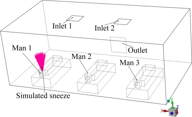
For Each AD proposal, six cases are simulated: (1) Steady state of a one-shot sneeze of Man 1; (2) Transient state of a constant sneeze of Man 1; (3) Steady state of a one-shot sneeze of Man 2; (4) Transient state of a constant sneeze of Man 2; (5) Steady state of a one-shot sneeze of Man 1; (6) Transient state of a constant sneeze of Man 1. The boundary conditions of each steady and transient state are also provided in Table 4 where the physical parameters of the virus particle are referred from Wong et al. (2015) and Gupta et al. (2009). Each transient case simulates a constant sneeze process from 0 to 100s. Fig. 8 shows a schematic view of the sneeze of Man 1 in Proposal A for a better understanding.
Fig. 8.
Model configuration of the sneeze from Man 1 in Proposal A.
To deal with the coupling between the pressure and velocity magnitude, the pressure implicit with splitting of operator is adopted to guarantee a better accuracy. Spatial discretization of the graient is selected to be least squares cell based, Momentum is third-order MUSCL, and other parameters such as energy, turbulent kinetic energy, turbulent dissipation rate are second order upwind.
The process of the simulation of each case is the same for the comparative study and the process sequence is given as follows: (1) Establish the geometric model using the software Solidworks; (2) According to Table 4, Generate the mesh configuration of each AD proposal and set proper boundary type using the software of CFD-ICEM; (3) Using the Continuous phase model and the Turbulence model, described in Sections 3.1, 3.2, to obtain the data of the steady state of the air flow pattern of each AD proposal through setting proper boundary conditions in the software of Ansys-Fluent 19.2; (4) Steady-state sneeze process of one-shot release and transient sneeze process for each man in each AD proposal is simulated using the Discrete phase model, established in Section 3.3, and the steady-state data of each AD proposal, obtained in the Step (3), as the initial condition. Date pf both steady state and transient state of the particle flow pattern is obtained. (5) Data extraction and analysis are organized for each AP evaluation and comparison among different AD proposals.
5. Results and discussion
5.1. First-stage analysis
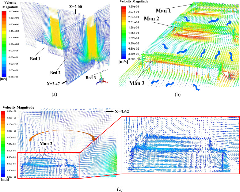
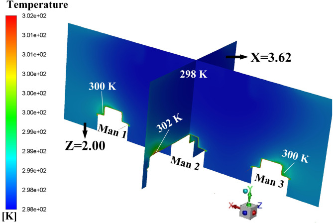
Proposals A to D is the four AD proposals in the first-stage schemes. Typical simulation results of these four proposals are provided in this section. Fig. 9 displays the air flow vector distributions in several focused locations of Proposal A. Fig. 9 (a) shows the air flow vector distributions under the two inlets where two obvious downward flows can be observed. Also, it can be seen that such downward flows will be held back before touching down the floor, which causing a flow scattering just above three men. The air flow vector distribution around these three men and the horizontal plane of Y = 0.45 m is illustrated in Fig. 9 (b) where X-direction horizontal flows are spotted which could be caused by the scattering flows in Fig. 9 (a). Note that the air on both sides of Man 3 flows towards this man which would cause cross-infection with a higher probability because virus particles diffused in the air could flow towards Man 3. One beneficial factor for Proposal A is that air upon the man surfaces is flowing upwards, as shown in Fig. 9 (c), which can bring the particles around the man moving to higher position. It can be primarily attributed to the metabolic heat from these men which bring a relatively high temperature around them which is shown in Fig. 10 . A natural convection where a high-temperature air will climb high may responsible for the upward flow around these three men.
Fig. 9.
Air flow vector distributions in Proposal A, (a) air flow vector distributions in the planes of Z = 2.00 m and X = 2.47 m; (b) air flow vector distributions upon surfaces of three men and the plane of Y = 0.45 m; (c) air flow vector distribution in the plane of X = 3.62 m (cross-section of Man 2).
Fig. 10.
Temperature distribution on the planes of X = 3.62 m and Z = 2.00 m.
Fig. 11 demonstrates the typical particle trajectories in the Proposal A where Fig. 11 (a) displays the particle trajectories from Man 1 and Fig. 11 (b) shows the particle trajectories from Man 2. In Fig. 11 (a), it can be observed that a fair part of the particles can reach the left side of Man 2 and a small part can even approach the foot area of Man 3, when Man 1 sneezes. That means a probable cross-infection may occur when Man 1 bring with the epidemic virus. In contrast, When Man 2 sneezes, the virus path-lines can be fairly confined within a narrow space which is beneficial to minimize the cross-infection. Such good performance could be attributed to the fact that the outlet is right opposite to Man 2 which means the ejected particle can be absorbed in a short period time. From Fig. 11, the maximum particle residence time can also be obtained where the time in Fig. 11 (a) is 163 s while that in Fig. 11 (b) is only 70.8 s. These quantitative data can verify the possible reasons drawn above that the released particles can be removed relatively fast when Man 2 sneezes. Table 5 gives the maximum particle residence times in Proposal A when each man sneezes respectively. Considering the randomness in the mobility of particles, numerical experiments for each particle source (Man 1, Man 2, and Man 3) were conducted three times. Therefore, Average maximum time for each particle source is given as well. The total maximum time (TMT) (418.5 s for Proposal A) which is the sum of the average maximum time for each particle source is given in the last column in Table 5 as an evaluation parameter of Proposal A. The TMT can reflect the mobility of the released particle and a smaller TMT can be supposed to have a lower probability of catching cross-infection.
Fig. 11.
Typical released particle trajectories in steady-state for Proposal A, (a) Man 1 as the virus particle source; (b) Man 2 as the virus particle source.
Table 5.
Maximum particle residence times of three-time numerical experiments in Proposal A. (Unit: s).
| Particle source | 1st experiment | 2nd experiment | 3rd experiment | Average time | Total time |
|---|---|---|---|---|---|
| Man 1 | 163 | 170 | 182 | 171.6 | 418.5 |
| Man 2 | 70.8 | 76.5 | 70.2 | 72.50 | |
| Man 3 | 173 | 167 | 183 | 174.3 |
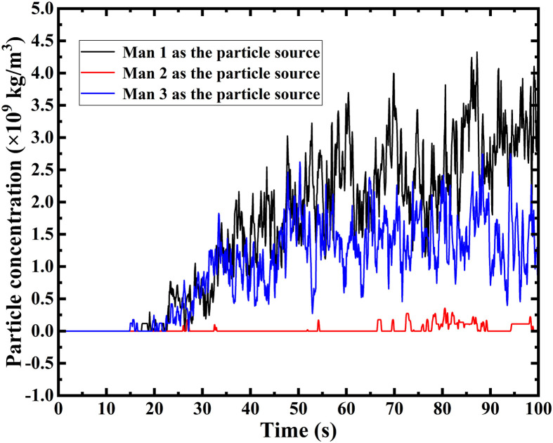
Transient simulation revolving Proposal A is also carried out. First of all, a focused area is defined as shown in Fig. 12 when taking Man 1 as the particle source. It can be concluded that when a certain man is the particle source, the entire surface of other two mans and their corresponding upper surfaces of the beds are highlighted as the focused area in each simulation. In order to reflect the probability of catching cross-infection, the surface-averaged particle concentration upon the focused area is selected as a critical evaluation parameter for each AD proposal. As shown in Fig. 13 , the transient particle concentration of the focused area for each particle source is plotted. Unsurprisingly, When Man 2 sneezes, the particle concentration of the focused area can be maintained to be very low, which agrees with the path-line demonstration in the steady-state. When Man 1 or Man 3 sneezes, the situation could be worse, which enhances the probability of cross-infection. Therefore, the hospital can place the most “dangerous” patients in the position of Man 2 to minimize the cross-infection under the Proposal A. However, the doctor can hardly identify the most “dangerous” patient when an emerging epidemic virus come at the very beginning time, which means patients will be arranged randomly. Given that, the superposition of the particle concentration in each time size of all the three particle sources, which is defined as the overall particle concentration (OPC), are given. The OPC of the Proposal A is calculated to be 2.613 × 10⁻⁶ kg/m3, which is a critical indicator to evaluate the Proposal A.
Fig. 12.
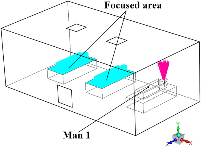
Demonstration of the focused area when Man 1 is the particle source.
Fig. 13.
Transient particle concentration of focused area for each man as the particle source in Proposal A.
Table 6 summarizes the TMT and OPC of the proposed four ADs in the first-stage. Generally, a lower TMT can have a lower OPC, which is beneficial to minimize the cross-infection. However, an exception is spotted, where the Proposal D has the lowest OPC and the second biggest TMT. In order to explain this particular case, typical air flow vector distributions and steady-steady particle trajectories for Proposal D are provided in Fig. 14 and Fig. 15 respectively. Fig. 14 (a) shows the air flow conditions around these three men where vertical flows and Z-direction horizontal flows are spotted. Unlike the X-direction flow in Proposal A shown in Fig. 9 (b), Such vertical flows and Z-direction flows can drive the possible virus particle away from these men. The red Y-direction flow represents the relatively high-speed flow from the two inlet in the floor. As the inlet flow is injected from floor to the ceiling, the upwards flow could be scattered in the ceiling which would cause vertical air circulations. As marked in Fig. 14 (b), two such vertical air circulations are existed in the plane of Man 3’s cross-section. Both clockwise and anticlockwise circulations would cause adverse flows, shown in Fig. 14 (b), which drives both the air and possible diffused virus particle to flow towards the Man 3. Also, favorable flows are marked in Fig. 14 (b) where the air on the upper surface of Man 3 flow upwards due to the relatively high temperature region.
Table 6.
Summary of the TMT and OPC of the AD proposals in the first-stage.
| Proposals | TMT (s) | OPC ( × 106 kg/m3) |
|---|---|---|
| A | 418.5 | 2.613 |
| B | 695.0 | 7.833 |
| C | 496.7 | 1.911 |
| D | 539.0 | 1.301 |
Fig. 14.
Air flow vector distributions in focused area in Proposal D, (a) air flow vector distributions upon surfaces of three men and the horizontal plane of Y = 0.45 m; (b) air flow vector distribution in the plane of X = 1.32 m (cross-section of Man 3).
Fig. 15.
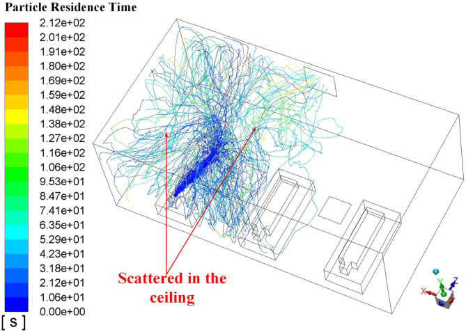
Typical released particle trajectories in steady-state in Proposal D (Man 1 is the particle source).
Analysis of the air flow conditions in Proposal D facilitates the understanding of the virus particle trajectory in this proposal, presented in Fig. 15 in which the Man 1 is the particle source. It can be spotted that as the air flow pattern is from the floor to the ceiling which is correspondent with the inlet air flow, the released particles is brought to the ceiling and spread in the top. Therefore, the majority of the lengthened TMT in Table 6 could be caused by the spreading time in the top area without the contact of other men in this ward. Frankly speaking, such lengthened TMT does no harm to the cross-infection. Considering the Proposal D possesses the lowest OPC which is the most critical and straightforward parameter to evaluate the AD proposal, extrapolated ADs from the Proposal D will be analyzed and optimized further in the following section.
5.2. Second-stage analysis
An interesting phenomenon in the first-stage analysis is spotted that the OPC of the Proposal C can be decreased by 75.6%, compared with that of the Proposal B. The only difference between these two proposals is the outlet is moved from the centreline of the Man 2 (in the Proposal B) to Man 3 (in the Proposal C). Such significant improvement encourages the authors to do the same alteration to the Proposal D. Therefore, the outlet of the Proposal E is moved to the position opposite to the Man 3. Also, the outlets in the Proposals E, F, and G are moved to the Wall 4 which are closer from the particle source (For detailed proposal structure, please refer to Fig. 5). Table 7 gives the detailed evaluation parameters of the proposals in the second-stage. It can be observed that the side-arranged outlet enlarges the OPC, which does not possess the expectant improvement. It can be attributed to the from-low-to-top particle cannot be absorbed by the outlet in time, which intensify the mobility of the particle.
Table 7.
Summary of the TMT and OPC of the AD proposals in the second-stage.
| Proposals | TMT (s) | OPC ( × 106 kg/m3) |
|---|---|---|
| E | 468.0 | 5.821 |
| F | 368.5 | 3.448 |
| G | 398.9 | 0.999 |
| H | 286.2 | 1.294 |
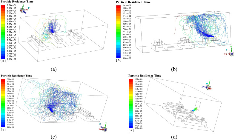
Enlightened by this observation, outlets in the Proposal F, G, and H are moved to the Wall 4, which is closer to the particle sources. As a result, both TMT and OPC experience a significant decrease. Proposals G and H can maintain the OPC around 1 × 10⁻⁶ kg/m3, which is a big progress in optimizing the AD. Particle trajectories of the Proposals G and H are illustrated in Fig. 16 . It can be seen that when Man 2 is the particle source, both G and H can perform well where the released particle can be absorbed immediately with a low probability of cross-infection, which is resulted from the upward flowing particle can reach the absorption region of the outlet without any further spreading. Such superiority can be spotted in Fig. 16 (d) where the all cluster of the particle can be delivered to the outlet with a maximum particle residence time of only 1.82 s, which also contributes to the lowest TMT so far. However, when Man 1 is the particle source as shown in Fig. 16 (c), the particle can be easily transported to the area of Man 2 in that the outlet is very close to the Man 2. It will enhance the probability of catching cross-infection for Man 2 when other people is firstly infected. The slightly higher OPC, compared with that of the G, can verify the conclusion above. What’s more, the outlet is usually not recommended to be arranged too close to the man because of the noise of the returning air flow.
Fig. 16.
Typical released particle trajectories in the Proposals G and H, (a) Man 2 is the particle source in the Proposal G; (b) Man 3 is the particle source in the Proposal G; (c) Man 1 is the particle source in the Proposal H; (d) Man 2 is the particle source in the Proposal H.
5.3. Final-stage analysis
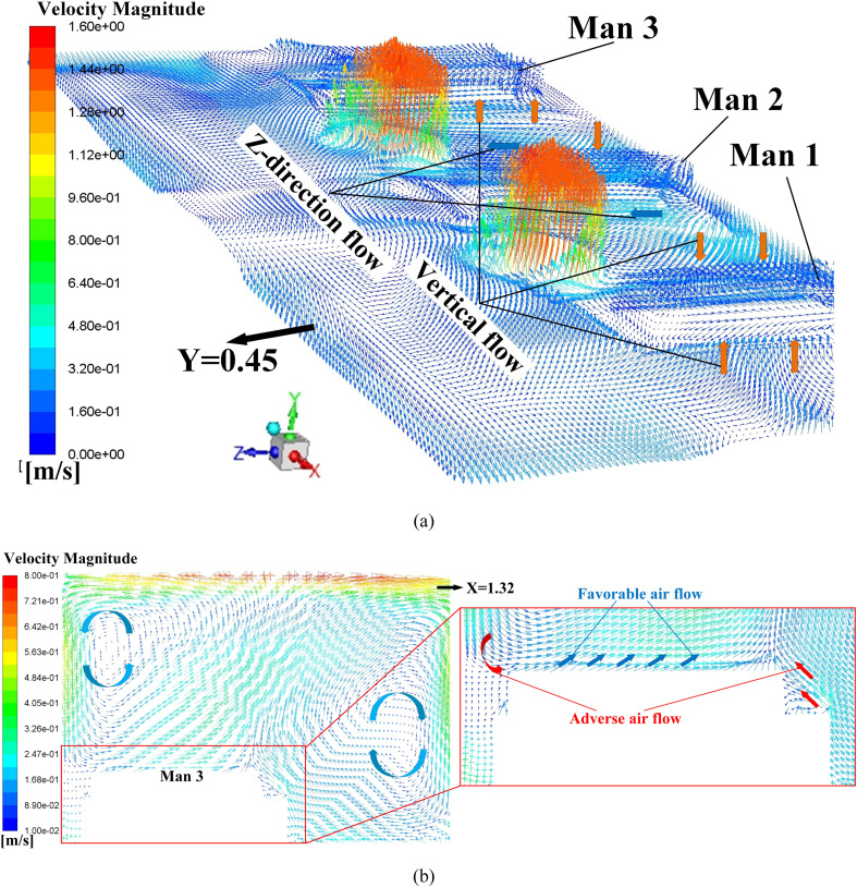
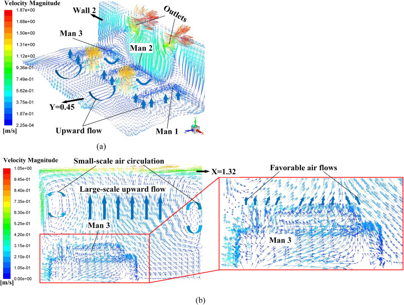
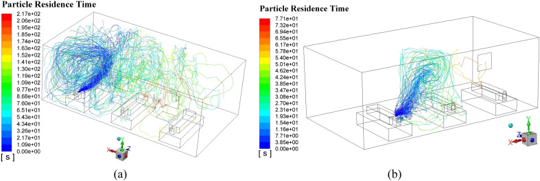
Enlightened by the results in Section 5.2, extrapolated ADs from the Proposal G are continuingly examined. In the final stage, each proposal has two outlets, chasing a lower TMT and OPC. Table 8 gives the results which manifest that the OPC in both proposals does decrease clearly and the Proposal J has the lowest TMT and OPC in this paper. In contrast, a relatively large TMT for the Proposal I is obtained. Fig. 17 may shed light on the possible cause of the excellent performance of Proposal J. A massive upward air flows are spotted around these three men, functioning as a protective screen to prevent the released virus particle approaching humans as presented in Fig. 17 (a). Additionally, Fig. 17 (b) shows that two tiny air circulations would occur in a high position, which are different with the huge ones in Fig. 14 (b). These two circulations are too small to cause adverse flows to Man 3. Instead, large-scale favorable upward flows exist around the Man 3, which would bring the low-position virus particle to a high location where these particles would be exhausted by the outlet immediately, shown in Fig. 17 (a). Fig. 18 shows the simulated particle trajectories of both proposes. It can be inferred that the maximum particle residence time when Man 1 is the particle source makes a majority part of the TMT of the Proposal I. The released particles can form a large vortex in the left-side of the Man 1, which lengthen the particle residence time and also, enhance the mobility of the particle. It can be observed that some particles can be moved to the position between Man 2 and Man 3 and absorbed by the Outlet 2. In comparison, the Proposal J can manage the particle more perfectly by placing the two outlets to the centreline of the gap space between the men, where the Outlet 1 can be closer to the Man 1.
Table 8.
Summary of the TMT and OPC of the AD proposals in the final-stage.
| Proposals | TMT (s) | OPC ( × 106 kg/m3) |
|---|---|---|
| I | 413.0 | 0.5105 |
| J | 283.2 | 0.3822 |
Fig. 17.
Air flow vector distributions in focused area in Proposal J, (a) air flow vector distributions upon surfaces of these three men, horizontal plane of Y = 0.45, and the Wall 2; (b) air flow vector distributions in the plane of X = 1.32 m (cross-section of Man 3) and upon the surface of Man 3.
Fig. 18.
Comparison of the Proposals I and J in terms of the particle trajectory when Man 1 is the particle source.
Through a three-stage analysis and comparisons, Proposal J is recommended to be the relatively optimized AD because the two developed evaluation parameter are both the most satisfying. By actively arranging positions of the inlet and outlet, the TMT can be decreased by nearly 60% and the OPC by 95%, which demonstrates that an optimized AD proposal does suppress the probability of cross-infection among patients in hospital wards.
6. Conclusion
In order to minimize the cross-infection of emerging epidemic virus in the very beginning to suppress the number of the people infected, Air distribution optimizations for a hospital ward are implemented using computational fluid dynamics. The sneeze process from virus carriers in a general hospital ward is stimulated where the flow pattern and life span of the released particle from the patient’s mouths is specially investigated. Virus particle mobility and probability of catching cross-infection are evaluated and optimized quantitatively with two specially-developed parameters - total maximum time (TMT) and overall particle concentration (OPC). Main reasons in optimizing the air distribution are provided in the following.
-
●
A bottom-in and top-out air distribution proposal is recommended to minimize the cross-infection, as it can bring the virus particle travelling in the ceiling and being exhausted from the ceiling.
-
●
Outlet closer to the men’s mouths is beneficial to confine the virus mobility and lower the probability of catching cross-infection significantly.
-
●
Generally speaking, a low OPC comes with a low TMT.
-
●
The TMT is an indirect parameter to reflect the probability of getting cross-infection while the OPC is the direct one. Therefore, proposals with a slightly higher TMT and lower OPC is acceptable.
-
●
Through smartly arranging the number and place of the outlets, the TMT can be decreased by nearly 60% and the OPC by 95%.
This paper uncovers a ward air pattern optimization method and a relatively optimized air distribution proposal, which is the Proposal J. Conclusions drawn in this paper can function as a guide in the restructuring the wards in hospital which treats respiratory infectious diseases specially. Note that the selected AC system may only function well for a fresh air supply mode. Admittedly, there are limitations in this paper according to the adopted assumption, which will be improved in our future follow-up study.
CRediT authorship contribution statement
Ji-Xiang Wang: Writing - original draft, Conceptualization, Formal analysis. Xiang Cao: Methodology, Investigation, Validation. Yong-Ping Chen: Project administration, Writing - original draft.
Declaration of competing interest
The authors declare that they have no known competing financial interests or personal relationships that could have appeared to influence the work reported in this paper
Acknowledgment
This work was co-supported by National Natural Science Foundation of China (Grant No. 51725602) and China Postdoctoral Science Foundation (No. 2020M671618). The authors would thank the editor and reviewers for their valuable efforts to polish up this manuscript.
Handling editor is Prof. Jiri Jaromir Klemeš
Appendix.
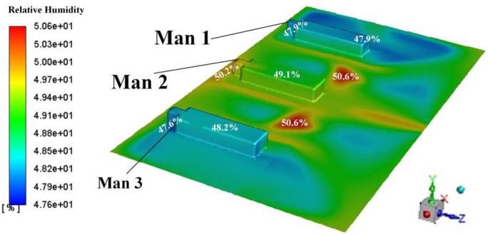
The effect of air humidity on the OPC is explored in this section. In order to reflect the effect of air psychrometry condition, a water-vapour species transport model is added in the governing equation as shown in Eq. (A1). Simulations considering the air humidity were conducted in Proposals A and B. The boundary condition subject to Table 4 except an addition item with the water-vapour mass fraction being 0.0099 (relative humidity: 50.6%). Such relative humidity also conforms to the GB51039-2014.
| (A1) |
where is the volume fraction of the water vapour in the air. is the diffusion coefficient of the water vapour.
Fig. A1 shows the distribution of relative humidity upon the surface of these three men and on the plane of Y = 0.45 m. It shows the relative humidity under such boundary condition can conform to the thermal comfort requirements in GB51039-2014. Table A1 shows the comparison of the OPCs in two simulations (dry air and moist air) under Proposals of A and B. It shows that simulation results using dry air can reflect the results using the moist air which is considered as a particle situation. Considering the lower computer costs, the authors adopted dry air as the continuous medium in the ward in this paper.
Fig. A1.
Distribution of relative humidity around the three men.
Table A1.
Comparison of the ORCs for dry air and moist air under Proposals of A and B
| Proposals | OPC for dry air ( × 106 kg/m3) | OPC for moist air ( × 106 kg/m3) | Relative error |
|---|---|---|---|
| A | 2.613 | 2.456 | 6.39% |
| B | 7.833 | 7.536 | 3.94% |
References
- Bourouiba L. Turbulent gas clouds and respiratory pathogen emissions: potential implications for reducing transmission of Covid-19. J. Am. Med. Assoc. 2020;323(18):1837–1838. doi: 10.1001/jama.2020.4756. [DOI] [PubMed] [Google Scholar]
- Bourouiba L., Dehandschoewercker E., Bush J. Violent expiratory events: on coughing and sneezing. J. Fluid Mech. 2014;745:537–563. [Google Scholar]
- Chen Y.P., Deng Z.L. Hydrodynamics of droplet passing through a microfluidic T-junction. J. Fluid Mech. 2017;819:401–434. [Google Scholar]
- Chen D., Nie W., Cai P., Liu Z. The diffusion of dust in a fully-mechanized mining face with a mining height of 7 m and the application of wet dust-collecting nets. J. Clean. Prod. 2018;205:463–476. [Google Scholar]
- Chuang H.C., Ho K.F., Lin L.Y. Long-term indoor air conditioner filtration and cardiovascular health: a randomized crossover intervention study. Environ. Int. 2017;106:91–96. doi: 10.1016/j.envint.2017.06.008. [DOI] [PubMed] [Google Scholar]
- Dbouk T., Drikakis D. On coughing and airborne droplet transmission to humans. Phys. Fluids. 2020;32 doi: 10.1063/5.0011960. [DOI] [PMC free article] [PubMed] [Google Scholar]
- Ganesh G.A., Sinha S.L., Verma T.N. Effect of inlet airflow direction on the indoor environment of a naturally ventilated room using CFD. Int. J. Eng. Adv. Technol. 2020;9(3):580–591. [Google Scholar]
- Ganesh G.A., Sinha S.L., Verma T.N. Numerical simulation for optimization of the indoor environment of an occupied office building using double-panel and ventilation radiator. J. Build. Eng. 2020;29 [Google Scholar]
- Gupta J.K., Lin C.H., Chen Q. Flow dynamics and characterization of a cough. Indoor Air. 2009;19:517–525. doi: 10.1111/j.1600-0668.2009.00619.x. [DOI] [PubMed] [Google Scholar]
- Handbook of prevention and treatment of the pneumonia caused by the Novel Coronavirus (2019-nCoV) 2020. http://www.chinadaily.com.cn/a/202002/03/WS5e380559a31012821727483d.html China Daily. [Google Scholar]
- Huang C., Wang Y., Li X., Ren L. Clinical features of patients infected with 2019 novel coronavirus in Wuhan, China. Lancet. 2020;395:497–506. doi: 10.1016/S0140-6736(20)30183-5. [DOI] [PMC free article] [PubMed] [Google Scholar]
- Ignatius T.S., Li Y., Wong T.W., Wilson T. Evidence of airborne transmission of the severe acute respiratory syndrome virus. N. Engl. J. Med. 2004;350:1731–1739. doi: 10.1056/NEJMoa032867. [DOI] [PubMed] [Google Scholar]
- Kim S.H., Chang S.Y., Sung M. Extensive viable Middle East respiratory syndrome (MERS) coronavirus contamination in air and surrounding environment in MERS isolation wards. Clin. Infect. Dis. 2016;63:363–369. doi: 10.1093/cid/ciw239. [DOI] [PMC free article] [PubMed] [Google Scholar]
- Li A., Ahmadi G. Dispersion and deposition of spherical particles from point sources in a turbulent channel flow. Aerosol Sci. Technol. 1992;16:209–226. [Google Scholar]
- Li H., Fan G., Cao L., Yang Y. A comprehensive investigation on the design and off-design performance of supercritical carbon dioxide power system based on the small-scale lead-cooled fast reactor. J. Clean. Prod. 2020;256 [Google Scholar]
- Li Q., Guan X., Wu P., Wang X. Early transmission dynamics in Wuhan, China, of novel coronavirus–infected Pneumonia. N. Engl. J. Med. 2020;382:1199–1207. doi: 10.1056/NEJMoa2001316. [DOI] [PMC free article] [PubMed] [Google Scholar]
- Li Y., Wang J.-X., Chen X. Can a toilet promote virus transmission? From a fluid dynamics perspective. Phys. Fluids. 2020;32 doi: 10.1063/5.0013318. [DOI] [PMC free article] [PubMed] [Google Scholar]
- Liu H., Cai C., Yan Y., Jia M., Yin B. Numerical simulation and experimental investigation on spray cooling in the non-boiling region. Heat Mass Tran. 2018;54:3747–3760. [Google Scholar]
- Milner J., Vardoulakis S., Chalabi Z., Wilkinson P. Modelling inhalation exposure to combustion-related air pollutants in residential buildings: application to health impact assessment. Environ. Int. 2011;37(1):268–279. doi: 10.1016/j.envint.2010.08.015. [DOI] [PubMed] [Google Scholar]
- Osterholm M.T., Moore K.A., Kelley N.S., Brosseau L.M. Transmission of Ebola viruses: what we know and what we do not know. mBio. 2015;6(2) doi: 10.1128/mBio.00137-15. [DOI] [PMC free article] [PubMed] [Google Scholar]
- Pang L., Xu J., Fang L. Evaluation of an improved air distribution system for aircraft cabin. Build. Environ. 2013;59:145–152. [Google Scholar]
- Pereira T., Marques F., Pereira F., Ribeiro D., Rocha S. The influence of the fabric filter layout of in a flow mass filtrate. J. Clean. Prod. 2016;111:117–124. [Google Scholar]
- Perlman S. Another decade, another coronavirus. N. Engl. J. Med. 2020;382:760–762. doi: 10.1056/NEJMe2001126. [DOI] [PMC free article] [PubMed] [Google Scholar]
- Scharfman B.E., Techet A.H., Bush J., Bourouiba L. Visualization of sneeze ejecta: steps of fluid fragmentation leading to respiratory droplets. Exp. Fluid. 2016;57:24. doi: 10.1007/s00348-015-2078-4. [DOI] [PMC free article] [PubMed] [Google Scholar]
- Shih T.H., Liou W.W., Shabbir A., Zhu J. A new eddy viscosity model for high Reynolds number turbulent flows. Comput. Fluids. 1995;24:227–238. [Google Scholar]
- Silvis M.H., Remmerswaal R.A., Verstappen R. Physical consistency of subgrid-scale models for large-eddy simulation of incompressible turbulent flows. Phys. Fluids. 2017;29 [Google Scholar]
- Sun Y., Alkhedhair A.M., Guan Z., Hooman K. Numerical and experimental study on the spray characteristics of full-cone pressure swirl atomizers. Energy. 2018;160:678–692. [Google Scholar]
- Verma T.N., Sahu A.K., Sinha S.L. Study of particle dispersion on one bed hospital using computational fluid dynamics. Mater. Today: Proceedings. 2017;4:10074–10079. doi: 10.1016/j.matpr.2017.06.323. [DOI] [PMC free article] [PubMed] [Google Scholar]
- Verma T.N., Sinha S. Numerical simulation of contaminant control in multi-patient intensive care unit of hospital using computational fluid dynamics. J. Med. Imaging Heal. Informatics. 2015;5(5) [Google Scholar]
- Verma T.N., Sahu A.K., Sinha S.L. Numerical simulation of air pollution control in hospital. In: Sharma N., Agarwal A., Eastwood P., Gupta T., Singh A., editors. Air Pollution and Control. Energy, Environment, and Sustainability. Springer; Singapore: 2018. [Google Scholar]
- Wang J.X., Li Y.Z., Zhang H.S., Wang S.N., Mao Y.F. Investigation of a spray cooling system with two nozzles for space application. Appl. Therm. Eng. 2015;89:115–124. [Google Scholar]
- Wang J.-X., Li Y.-Y., Liu X.-D, Cao X. Virus transmission from urinals. Phys. Fluids. 2020 doi: 10.1063/5.0021450. In press. [DOI] [PMC free article] [PubMed] [Google Scholar]
- Wang J.X., Li Y., Liu X., Shen C. Recent active thermal management technologies for the development of energy-optimized aerospace vehicles in China. Chinese J. Aeronaut. 2020 doi: 10.1016/j.cja.2020.06.021. In press. [DOI] [Google Scholar]
- Wang J.X., Li Y.Z., Yu X.K., Li G.C., Ji X.Y. Investigation of heat transfer mechanism of low environmental pressure large-space spray cooling for near-space flight systems. Int. J. Heat Mass Tran. 2018;119:496–507. [Google Scholar]
- Wang J.X., Guo W., Xiong K., Wang S.N. Review of aerospace-oriented spray cooling technology. Prog. Aerosp. Sci. 2020;116 [Google Scholar]
- Wang J.X., Li Y.Z., Li J.X., Li C., Zhang Y., Ning X.W. A gas-atomized spray cooling system integrated with an ejector loop: ejector modeling and thermal performance analysis. Energy Convers. Manag. 2019;180:106–118. [Google Scholar]
- Wang J., Sun L.Y., Zou M.H., Gao W. Bioinspired shape-memory graphene film with tunable wettability. Sci. Adv. 2017;3(6) doi: 10.1126/sciadv.1700004. [DOI] [PMC free article] [PubMed] [Google Scholar]
- Wong L.T., Yu H.C., Mui K.W., Chan W.Y. Drag constants of common indoor bioaerosols. Indoor Built Environ. 2015;24:410–413. [Google Scholar]
- Yang S., Lee G.W.M., Chen C.M., Wu C.C., Yu K.P. The size and concentration of droplets generated by coughing in human subjects. J. Aerosol Med. 2007;20:484–494. doi: 10.1089/jam.2007.0610. [DOI] [PubMed] [Google Scholar]
- Yin S., Nie W., Liu Q., Hua Y. Transient CFD modelling of space-time evolution of dust pollutants and air-curtain generator position during tunneling. J. Clean. Prod. 2019;239 [Google Scholar]
- Yu H.C., Mui K.W., Wong L.T., Chu H.S. Ventilation of general hospital wards for mitigating infection risks of three kinds of viruses including Middle East respiratory syndrome coronavirus. Indoor Built Environ. 2017;26(4):514–527. [Google Scholar]
- Zhang C.B., Wu S.C., Yao F. Evaporation regimes in an enclosed narrow space. Int. J. Heat Mass Tranf. 2013;138:1042–1053. [Google Scholar]
- Zhang T., Yin S., Wang S. An under-aisle air distribution system facilitating humidification of commercial aircraft cabins. Build. Environ. 2010;45:907–915. doi: 10.1016/j.buildenv.2009.09.010. [DOI] [PMC free article] [PubMed] [Google Scholar]
- Zhang T., Li P., Zhao Y. Various air distribution modes on commercial airplanes. Part 1: experimental measurement. HVAC R Res. 2013;19:268–282. [Google Scholar]
- Zhang Y., Liu J., Pei J. Performance evaluation of different air distribution systems in an aircraft cabin mockup. Aero. Sci. Technol. 2017;70:359–366. [Google Scholar]
- Zhou W., Nie W., Liu X. Optimization of dust removal performance of ventilation system in tunnel constructed using shield tunneling machine. Build. Environ. 2020;173:106745. [Google Scholar]
- Zhu N., Zhang D.Y., Wang W., Li X. A novel coronavirus from patients with pneumonia in China. N. Engl. J. Med. 2020;382:727–733. doi: 10.1056/NEJMoa2001017. [DOI] [PMC free article] [PubMed] [Google Scholar]


