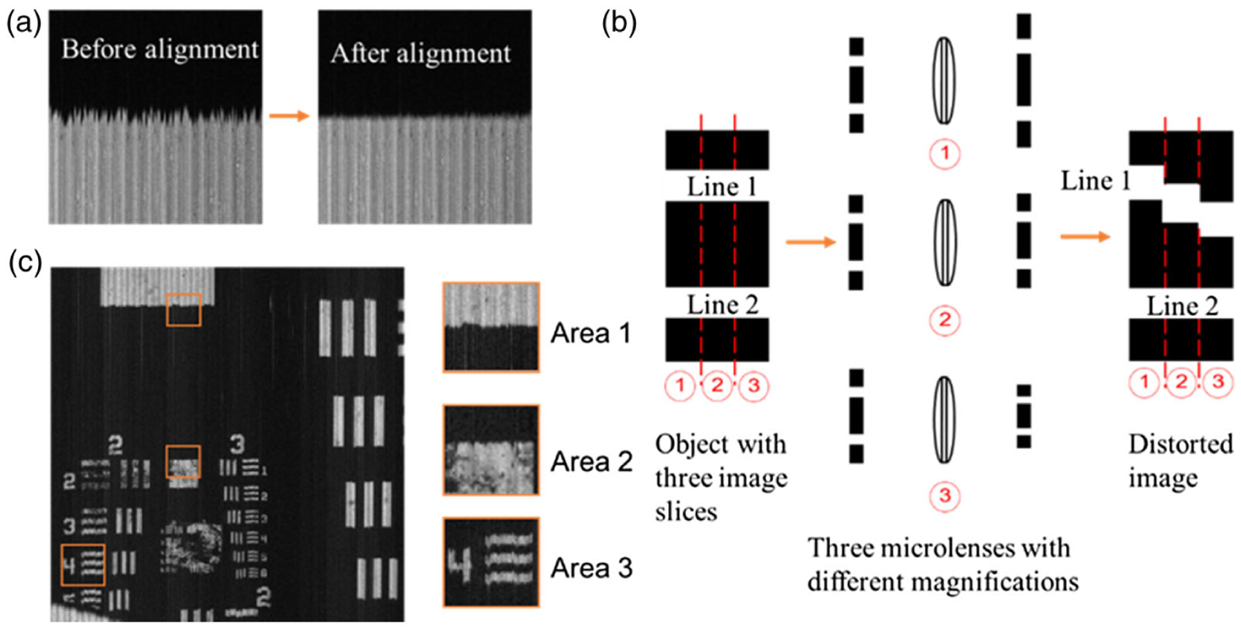
Fig. 2.

Edge alignment method. (a) Image slices alignment. (b) Distorted edge due to the variation in the magnification ratio of adjacent image slices. (c) Reconstructed image at 532 nm. The three insets show the zoomed view of the boxed areas. Area 3 shows the bars of group 2 element 4, indicating 5.66 lp/mm.
