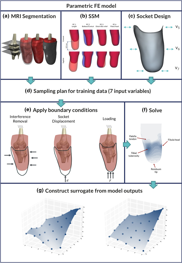
Fig. 1.
Flowchart of the developed workflow. a Segmentation of the MRI scan and creation of the FE mesh, b SSM from PCA of 30 surface scans, c parametric model of TSB socket design, showing the three design variables used to control the press fit at the proximal, mid and distal regions, d Latin hypercube sampling plan of the seven input variables to the parametric model, e application of model boundary conditions including the socket donning and loading, f solution of the FE models as training data, highlighting the regions of interest across the limb, g creation of the surrogate model based on the FE simulations. Dots denote the training data, and the surface shows the fitted function

