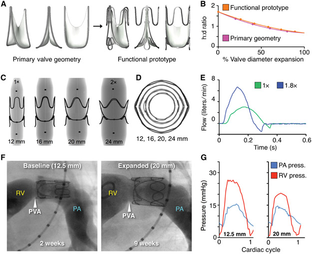
Fig. 5. Functional prototype design and in vivo proof-of-concept of valve expansion in a growing lamb model.
(A) CAD models of primary valve geometry and functional prototype containing added structural support features to optimize valve geometry for mechanical expansion. (B) Valve expansion geometry (change in aspect ratio with radial expansion) for the primary valve geometry (pink line) and functional prototype (orange line), h:d = height to diameter ratio (C) X-ray images of laser-cut stainless-steel functional valve prototypes being expanded via serial balloon dilation. Black dots are x-ray opaque markers on the balloon, denoting zone of constant diameter (D) Top-view x-ray transmission images showing geometry of the functional prototype with expansion from 1X to 2X diameter. (E) In vitro flow loop testing of functional prototype at two polar expansion states, 1X (green) and 1.8X (blue). Plots show the valve flow cycle at both expansion states. (F) Representative right ventricular (RV) angiograms in a lamb showing the expandable biomimetic valve prototype in its baseline (12.5 mm ID) and expanded (20 mm ID, after 3 separate balloon dilation procedures) configuration at 2- and 9-weeks post implantation, respectively. RV = right ventricle, PA = pulmonary artery, PVA = native pulmonary valve annulus (G) Representative right ventricular and pulmonary artery pressures recorded at two states of valve expansion, (left:1X, 12.5mm ID) and (right: 1.6X, 20mm ID) at 2 and 9 weeks after implantation.

