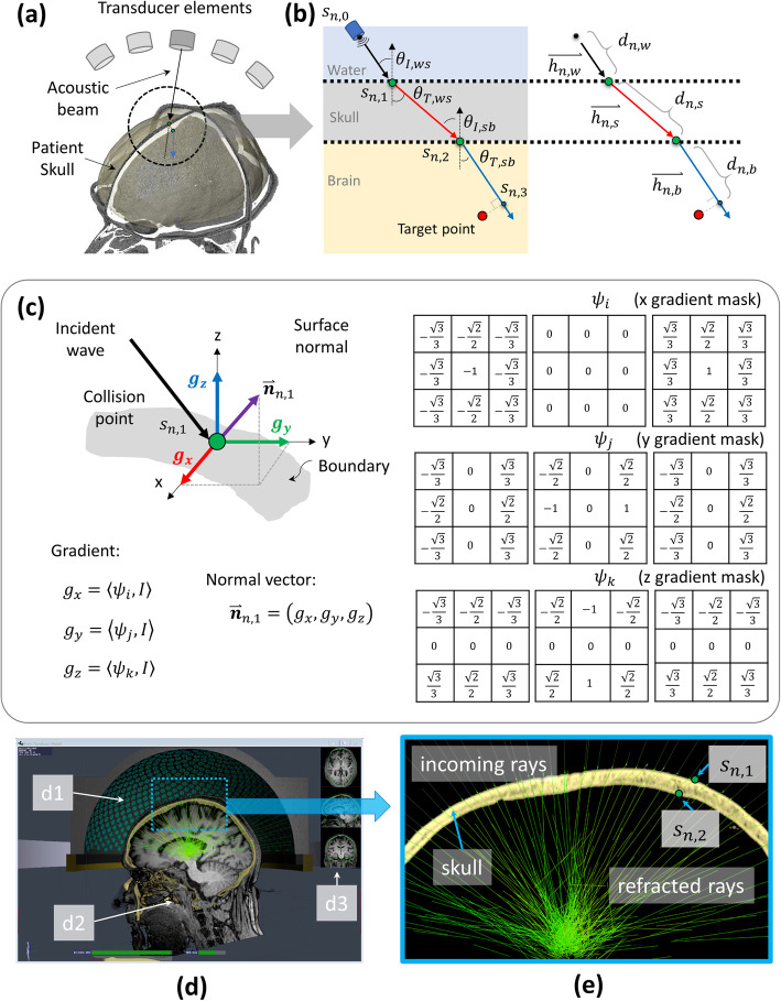
Fig. 5.
Overview of proposed ray-tracing based phase correction. a Some of the 1024 elements of the clinical focused ultrasound (FUS) transducer and reconstructed 3D patient head based on computed tomography (CT) images. A threshold-based collision point detection was applied to define the intersection point between incident vector and skull. b The refraction diagrams on water-to-skull and skull-to-brain boundary. c The edge operator on three axis and the equations to estimate the normal vector of the skull surface on the basis of the defined collision point. d Overview of developed graphic user interface (GUI) of the Kranion software. Illustrating the FUS transducer (d1) and magnetic resonance imaging (MRI)–CT registration (d2 and d3) of the same patient. e Zoomed view of the blue rectangular depicted in (d). The refracted rays (green lines) on sn, 1 and sn, 2 of 1024 channels were rendered in a sub-second speed. Note that the MRI image was not utilized in phase correction experiment. The MRI image shown in this figure is to show the MRI-CT image registration capability of developed software

