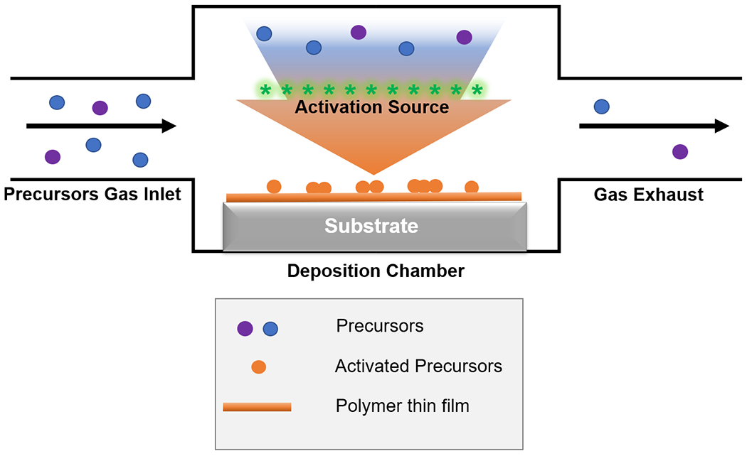
Figure 1. Generalized schematic of CVD techniques.

A CVD reactor typically consists of 3 main parts: precursors gas inlet, deposition chamber and gas exhaust. Blue and purple circles represent precursors in the vapor phase, orange circles activated/reactive species on the substrate surface, and orange line the as-deposited polymer thin film.
