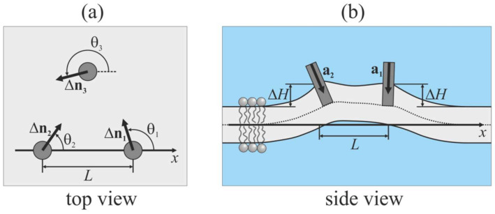
Figure 3.
Schematic illustration of configuration of peptides embedded into the upper monolayer of the membrane (shown by light gray color). (a) Top view; (b) side view. Embedded peptides are shown as gray circles (panel (a)) or gray rectangles (panel (b)). a is the unit vector directed along the longitudinal peptide axis; Δn is the projection of a onto the Oxy plane; θ is the angle between the Ox axis and Δn; L is the distance between peptides; ΔH is the vertical position of center of the peptide intersection with the neutral surface of the upper monolayer relative to the position of this surface far from embedded peptides.

