. 2020 Jul 15;9:e59991. doi: 10.7554/eLife.59991

Figure 5. Proposed mechanism of Ca2+-dependent control.

Left, structure of the holocomplex under resting [Ca2+]IMS conditions. MCU and EMRE are depicted with cylindrical helices; MICU1 and MICU2 are represented as semitransparent surfaces, with α1 and α2 helices of the UID as ribbons. The lipid membrane (gray) is based upon an atomistic model (Figure 5—figure supplement 1) . The UID blocks the pore (gray tube). Following elevation of [Ca2+]IMS, Ca2+ binding causes the MICU1-MICU2 heterodimer to bend (the Ca2+-bound MICU1-MICU2 structure is depicted with the channel in the center and right panels). The center panel indicates that bending would dislodge the UID from its receptor site in order to avoid thermodynamically unfavorable interactions of MICU2 with the membrane (‘X’). The dislodged Ca2+-bound MICU1-MICU2 heterodimer would no longer block the pore, thereby allowing Ca2+ permeation through the channel, and it would be free to interact with the membrane (right). Upon the return of resting [Ca2+], the heterodimer would resume its blocking conformation (left). One MICU1-MICU2 heterodimer is depicted and only one can bind to the receptor on the channel at a time but multiple MICU1-MICU2 heterodimers may be associated with the channel. A brown line depicts a hypothetical interaction of the acidic C-terminus of EMRE with MICU1.

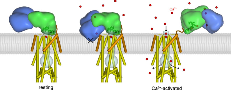
Figure 5.

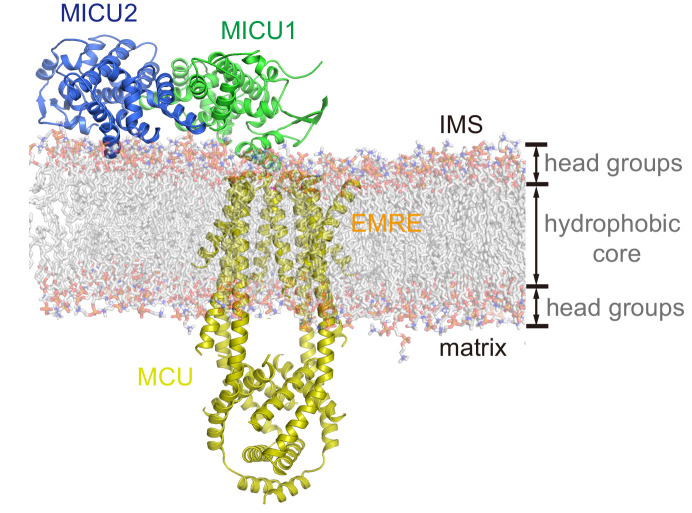
Figure 5—figure supplement 1. Atomistic model of the resting holocomplex in a lipid bilayer.

Figure 5—figure supplement 1.

The holocomplex was modeled into a DPPC (1,2-dipalmitoyl-sn-glycero-3-phosphocholine) lipid bilayer, using CHARMM-GUI (http://www.charmm-gui.org/). MCU, EMRE, MICU1 and MICU2 are shown as cartoons. DPPC molecules are shown as transparent sticks.
Figure 5—figure supplement 2. Model of a dimeric human MCU-EMRE-MICU1-MICU2 complex under resting [Ca2+] conditions.

Figure 5—figure supplement 2.

The complex was modeled based on holocomplex and the dimeric human MCU-EMRE complex (PDB:6O58). MCU, EMRE, MICU1 and MICU2 are shown as cartoons with transparent molecular surfaces and colored gold, orange, green and blue, respectively. A curved mitochondrial inner membrane is depicted as a transparent gray arc. Dimerization of channels is due to the NTDs of human MCU. As shown, MICU1-MICU2 regulatory complexes could bind to both channels of the dimer without sterically interfering.
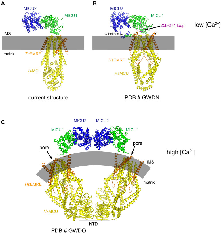
Figure 5—figure supplement 3. Comparisons of the TcMCU-EMRE-MICU1-MICU2 holocomplex structure with structures of human MCU-EMRE-MICU1-MICU2 holocomplexes.

Figure 5—figure supplement 3.

(A–B) Low [Ca2+] structures. (A) TcMCU-EMRE-MICU1-MICU2 holocomplex structure reported here. (B) Holocomplex containing human MCU, EMRE, MICU1, and MICU2 subunits (PDB # GWDN). An ordered loop of MICU1 (amino acids 258–274) is indicated, as are the C-helices of MICU1 and MICU2, which are also ordered in that structure. (C) Structure of a holocomplex comprising human MCU, EMRE, MICU1, and MICU2 that was determined at high (2 mM) [Ca2+] (PDB # GWDO). A dimer of channels present in the cryo-EM sample is formed by interactions between the NTDs. For each channel, a Ca2+-bound MICU1-MICU2 regulatory complex is located adjacent to the pore and no longer occludes it.