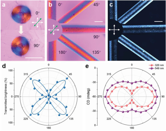
Figure 4.

Responsive optical appearance and polarized light control. a) POM‐λ images showing the same Maltese cross pattern at 0°and 90°. b) POM‐λ images showing the optical appearance as a function of the rotation angle of GOLC fibers, and c) corresponding POM images. d) Transmitted brightness variation of linearly polarized light through the GOLC fibers as the angle changes. e) CD intensity variation of right‐handed circularly polarized light through the GOLC fibers as the angle changes at a wavelength position of 320 and 549 nm, respectively. Scale bars, 500 µm.
