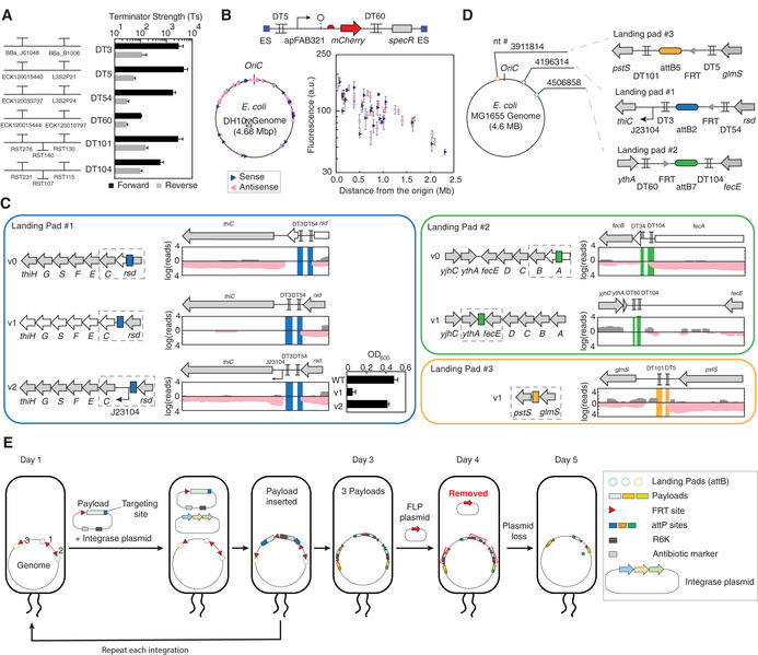
Figure 1. Design of insulated genetic landing pads.

- The six bidirectional double terminators are shown. The terminator strength is shown, calculated as described in the Materials and Methods. Terminator sequences are provided in Appendix Table S1. The means of three experiments performed on different days are shown, and the error bars are the standard deviation of these measurements.
- The transposon library screen in E. coli DH10β. The construct shown was randomly integrated into the genome (ES, end sequences). Sense and antisense insertions are denoted by the navy right and pink left triangles, respectively. Detail information (location, expression levels, and OD600) of the insertion locations is provided in Appendix Table S2. The means of three experiments performed on different days are shown, and the error bars are the standard deviation of these measurements.
- The genomic impact of the landing pad locations. RNA‐seq was performed; sense and antisense transcripts are shown in gray and pink, respectively. The dashed squares show the regions of the genome shown in the transcriptional profiles. Genes colored white are those for which we observed large changes upon the insertion of the landing pads. The growth (OD600) of E. coli MG1655 strains harboring Landing Pad #1 v1 and v2 in Thamine‐free medium is shown. The means of three experiments performed on different days are shown, and the error bars are the standard deviation of these measurements.
- Final selection of three Landing Pads.
- Schematic showing the steps and time required to insert multiple payloads into the genome. A detailed protocol and the result of integration are provided in Appendix Note S1.
