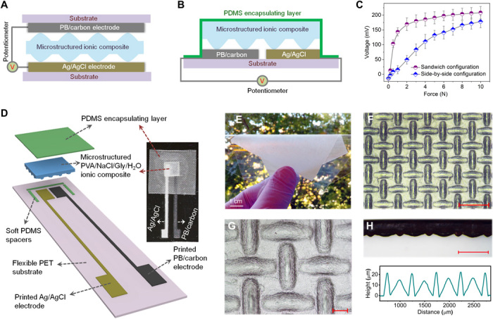
Fig. 2. All-solution–based fabrication of the potentiometric mechanotransducers.

(A and B) Schematic illustrations showing the mechanotransducers with sandwich structure (A) and side-by-side electrode configuration (B). (C) Response behaviors of mechanotransducers with different configurations. The contact area of the applied force is ≈16 mm2. (D) Schematic layout and photograph of the potentiometric mechanotransducers fabricated through an all-solution processing approach. See fig. S4 for the fabrication process. (E) Picture of a microstructured PVA/NaCl/glycerol (Gly)/water ionic composite film attached on a PET substrate. (F and G) Optical micrographs showing the created microstructure on the surface of the ionic composite via a mesh-molding strategy. See fig. S5 for the whole process flow. Scale bars, 500 μm (F) and 100 μm (G). (H) Cross-sectional morphology and surface profile of the microstructured ionic composite. Scale bar, 500 μm. Photo credit: X.W., University of California, Berkeley.
