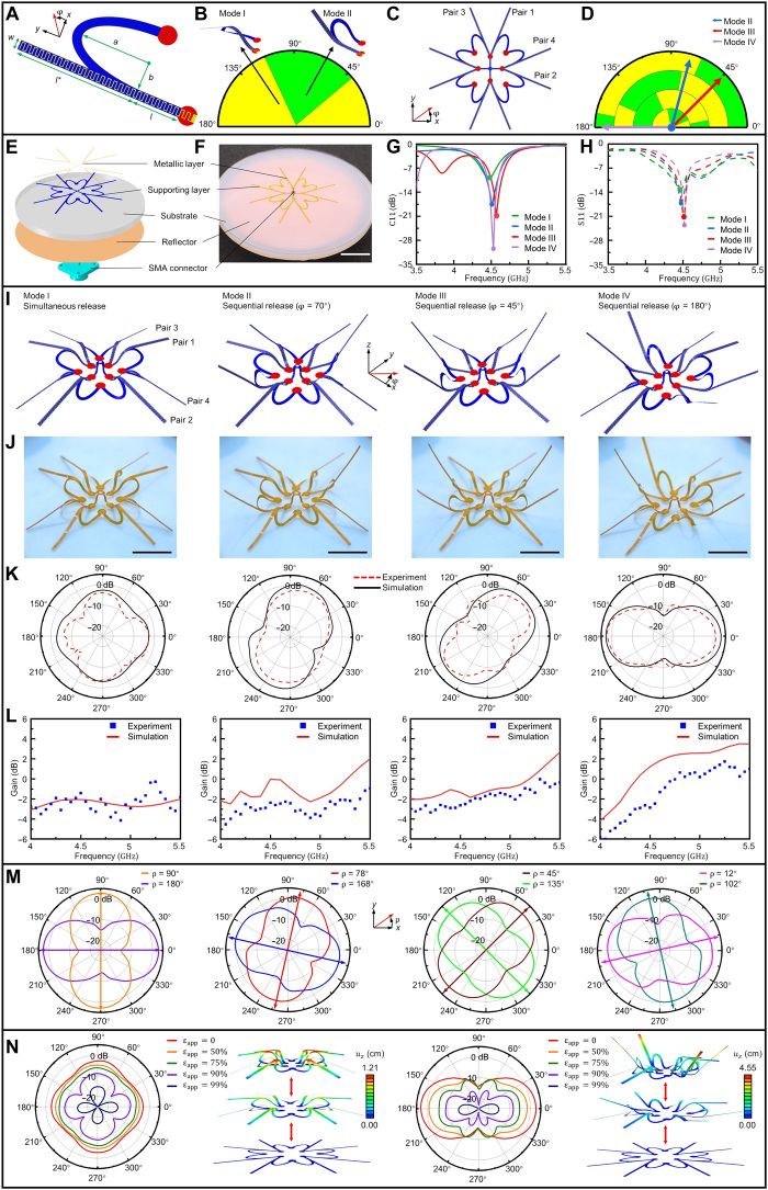
Fig. 4. A multimodal antenna with reconfigurable radiation pattern.
(A and B) 2D precursor and phase diagram of a ribbon-shaped reconfigurable antenna. (C and D) 2D precursor and phase diagram of a multimodal antenna consisting of four pairs of reconfigurable components in (A). (E and F) Exploded view illustration and optical images of the antenna. (G and H) Results of electromagnetic simulations (G) and experimental measurements (H) for the return loss (S11) of the antenna at different operation modes. (I and J) FEA results and optical images of the antenna at different operation modes. (K) H-plane radiation patterns of the antenna at different operation modes. (L) Results of electromagnetic simulations and experimental measurements for the gain of the antenna. (M) Beam scanning of the antenna enabled by the distinct stable configurations with rotational symmetry and/or mirror symmetry. The corresponding release paths are (90°; 180°), (70°; 160°), (45°; 135°), and (20°; 110°), respectively. (N) Tunable H-plane radiation patterns of the antenna at modes I and IV by applying different levels of biaxial stretching to the substrate. The evolving 3D configurations with the biaxial stretching are also included. Scale bars, 2 cm. Photo credit: K.B., Tsinghua University.

