Fig. 5.
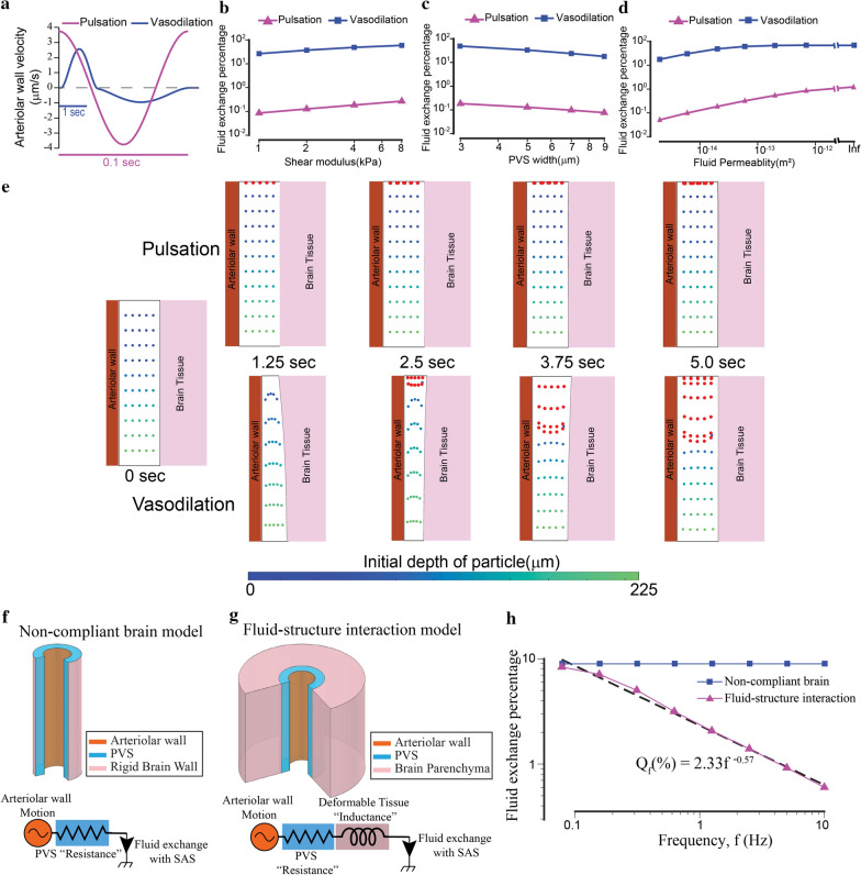
Functional hyperemia but not arteriolar pulsation drives appreciable fluid exchange between the PVS and the SAS. The difference in the fluid exchange driven by the two mechanisms is because of the deformability of brain tissue. a The arteriolar wall velocities induced by pulsations and hyperemia used in our simulations are similar in magnitude. The time scales are different for pulsations and hyperemia. b–d Vasodilation drives two orders of magnitude higher fluid exchange between the PVS and subarachnoid space compared to heartbeat driven pulsations. The plots show the changes in fluid exchange percentage, the percentage of fluid in the PVS exchanged with the SAS, with change of model parameters. The model predicts that compared to arteriolar pulsations, the vasodilation driven fluid exchange percentage is two orders of magnitude higher. This difference is similar for different values of elastic modulus of the brain (b), the width of the PVS (c) and the fluid permeability of the PVS (d). In (d), when the permeability is infinite, Darcy-Brinkman’s law transforms into Navier–Stokes’ law for fluid flow. All the plots are made on a log–log scale because the parameters were changed by 1–3 orders of magnitude. e Comparison of particle motion in the fluid of the PVS during arteriolar pulsations and vasodilation. The blue-green dots represent fluid in the PVS, with the colormap showing the initial position (depth) of the fluid particle in the PVS. Fluid particles near the SAS (red dots) are added once every 0.5 s to the simulation to simulate fluid mixing between the PVS and the SAS. There is very little fluid movement driven by arteriolar pulsations. Vasodilation drives appreciable fluid exchange between the PVS and the SAS. These calculations were performed with fluid permeability, ks = 2 × 10⁻¹⁴ m2 and tissue shear modulus µs = 4 kPa. f Geometry for a model in which the brain is a rigid boundary to the PVS (top) and the equivalent circuit diagram (bottom). The driver for fluid flow is the arteriolar wall motion. The flow resistance of the PVS can be modelled by a simple resistor is independent of the frequency of the arteriolar wall movement. g Geometry for the fluid–structure interaction model with a deformable brain (top) and the equivalent circuit diagram (bottom). The driver for fluid flow is the arteriolar wall motion. The total flow resistance of the system can be modelled by a resistance from the PVS and an inductance because of the deformable tissue. In this model, the flow resistance of the system increases with increase in the frequency of the arteriolar wall motion. This means that for arteriolar wall motion at high frequency, less fluid will be exchanged between the PVS and the SAS. h Plot shows the relation between fluid exchange percentage and frequency of arteriolar wall motion. The arteriolar wall motion was given by a 4% peak-peak sinusoidal wave with different frequency values. The default values were used for all other parameters (see Table 1). For very low frequencies (< 0.1 Hz), the fluid exchange driven by the arteriolar wall is same whether or not brain deformability is taken into account. For higher frequencies, the fluid exchange percentage has an inverse power law relation with the frequency of arteriolar wall motion

