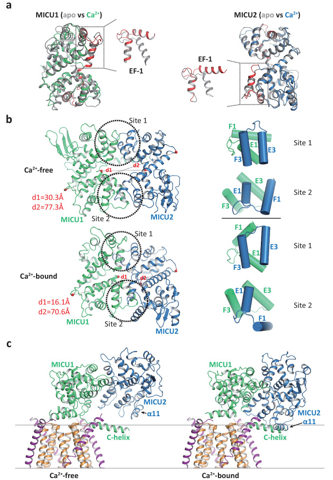
Figure 5. Structural comparison of the MICU1-MICU2 dimers in the apo and Ca2+-bound states.
(a) Superimposition of individual MICU1 (left) or MICU2 (right) subunit structures between the apo (grey) and the Ca2+-bound (MICU1 in green and MICU2 in blue) states. EF-1 and EF-3 motifs of MICU1 and MICU2 in Ca2+-bound states are colored red. (b) Structural comparison of the MICU1-MICU2 heterodimer in the apo (upper) and Ca2+-bound (lower) states with the inter-subunit contact sites circled. Grey dashed lines mark the inter-subunit distances between the Ca atoms (red spheres) of MICU1’s Met442 and MICU2’s His396 (d1) and between the Ca atoms of MICU1’s Val318 and MICU2’s Gly274 (d2). Right panels show the inter-subunit packing between EF-1 and EF-3 at each contact site in the absence (upper two) and presence (lower two) of Ca2+. (c) Left, structure of the blocked MCU-EMRE channel pore by a MICU1-MICU2 dimer in the apo state. Right, hypothetical model of the channel pore being blocked by the Ca2+-bound MICU1-MICU2 dimer. The model is generated by superimposing the MICU1 subunit of the Ca2+-bound MICU1-MICU2 dimer onto the MICU1 of the apo, blocked uniplex.

