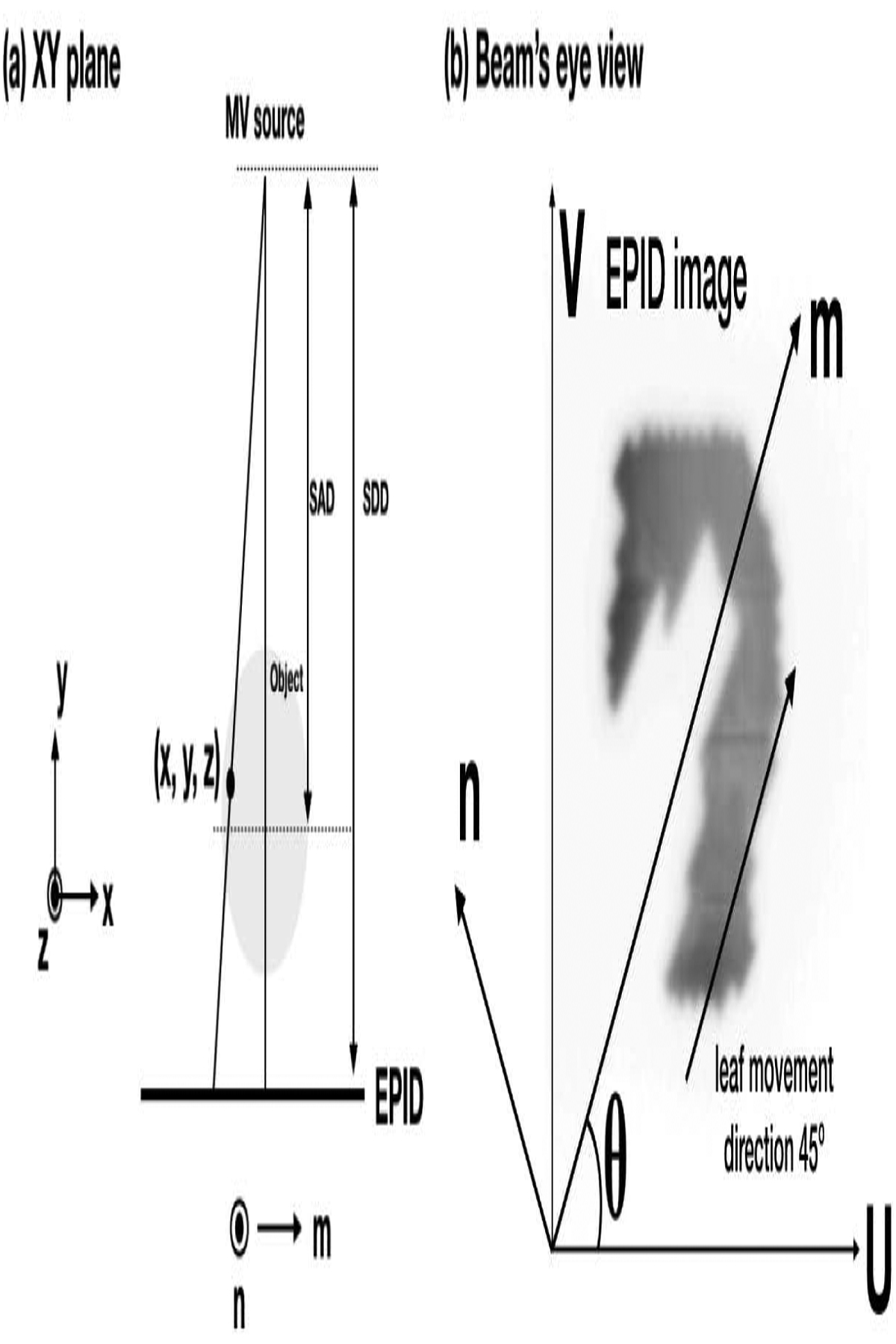
Fig. 1.

Geometry of VMAT-CT reconstruction. (u, v) is the generic EPID image coordinate and is aligned with the panel’s edge, while (m, n) is chosen so that m is parallel to MLC leaf movement direction. (a) The X-Y plane when gantry angle is 0°, notice z and n are parallel. (b) A typical beam’s eye view. (m, n) is rotated θ degree relative to (u, v) counter clockwise when the collimator angle is θ.
