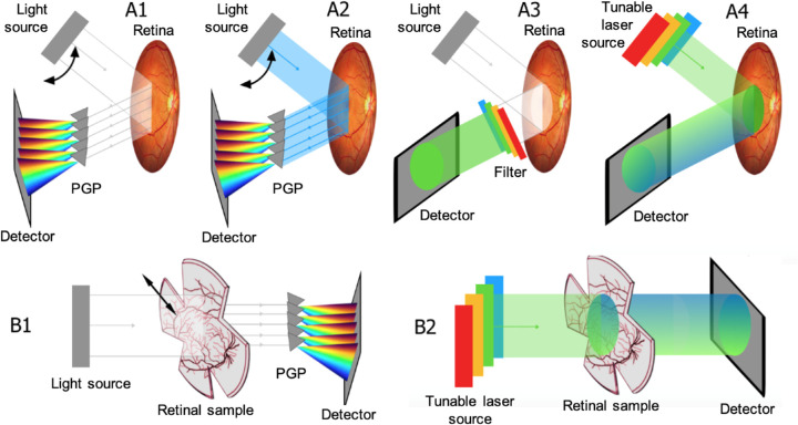
Figure 1.
Illustration of different hyperspectral modes. (A) In vivo set-ups for retinal HSI in reflectance mode: (A1) HSI with a PGP (grey triangles); (A2) identical to the set-up in A1 but in autofluorescence mode; The double black arrow indicates the turning movement of the illumination source. (A3) HSI with LCTF in imaging path and (A4) HSI method based on LCTF in illumination path or based on TLS. (B) Ex vivo set-ups for retinal HSI in transmission mode. Set-up (B1) is based on a PGP array analogous to A1. (B2) shares an identical illumination as in A4. The color gradient in A4 and B2 refer to Stokes shift.

