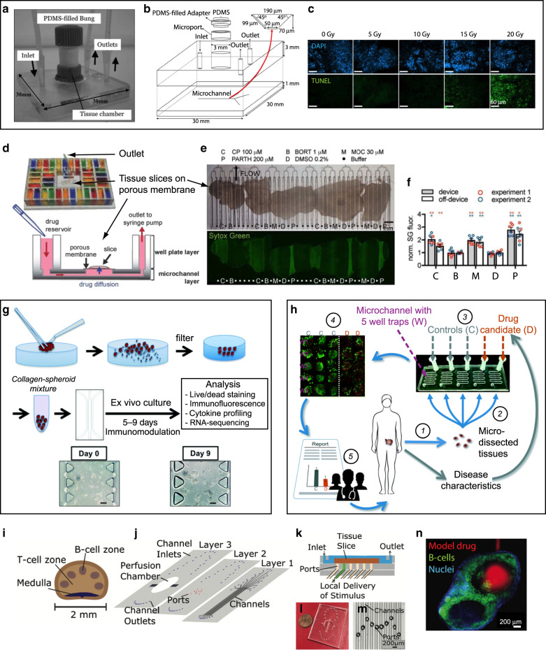
Fig. 3. Microfluidic interrogation of cancer and lymphatic tissue.
a–c A Y-shaped microchannel for measuring the responses of human head and neck squamous cell carcinoma biopsies to radiation. a Photograph of the device. b Schematic diagram of the device. c Micrographs showing DAPI (nuclei, top images) and TUNEL staining (DNA fragmentation after irradiation, bottom images) on lymph neck node metastases following microfluidic culture with control no irradiation (0 Gy) or different single-dose irradiations (5, 10, 15, and 20 Gy). Adapted with permission from ref. 74. d–f Microfluidic platform for drug sensitivity testing of intact tumor slices. d Photograph of the multi-well platform, with the inlet wells filled with food-coloring dyes (top); cross-section schematic of the device, showing a slice atop the porous membrane (bottom). e 48-h-long delivery of a panel of cancer drugs consisting of cisplatin (C or CP, 100 µM), bortezomib (B or BORT, 1 µM), mocetinostat (M or MOC, 30 µM), and parthenolide (P or PARTH, 200 µM), as well as a vehicle control (DMSO, 0.2%) and intervening buffer channels (•) to 5 U87 glioma xenograft flank tumor slices on the device. The top image is a brightfield micrograph at the beginning of the experiment, and the bottom image is a fluorescence micrograph after bathing the slices with SYTOX Green, a cell death indicator, at the end of the experiment. f The cell death readouts are consistent from experiment to experiment and comparable to off-device controls. Adapted with permission from ref. 77. g Workflow for drug treatment of micro-dissected tumors (µDTs), showing mincing, filtration, resuspension in collagen gel, culture in a central microchannel, drug treatment, and analysis. Delivery of immunomodulators is performed through the two side channels. Adapted with permission from ref. 66. h Workflow for drug treatment and analysis of µDTs placed into microfluidic PDMS traps. Each channel is perfused independently and contains 5 traps. Adapted with permission from ref. 67. i–n Microfluidic devices for probing lymph node slice cultures. i Schematic of the lymph node structure. j Exploded schematic showing the three layers of the device. k Cross-section schematic of the assembled device. l Top-view photograph of the device. m Micrograph of the center portion of the device containing a set of apertures for delivery of solutions to the tissue. n Local stimulation of the T-cell region of a lymph node slice with a model drug (Alexa Fluor-647-Glucose-BSA, red). To identify B-cell zones, live slices were also stained with FITC-anti-mouse B220 (green) and Hoechst (blue). Adapted with permission from ref. 95

