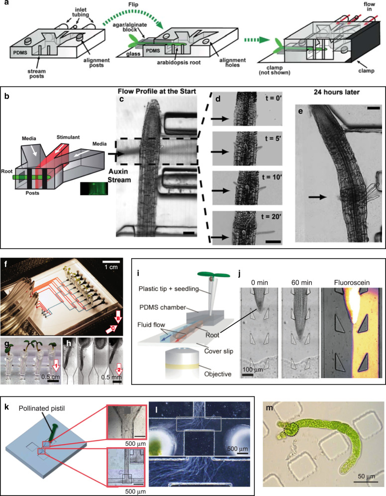
Fig. 5. Microfluidic devices for probing plant tissues.
a–e A microfluidic device for interrogating Arabidopsis roots. a Schematic of the assembly of the microfluidic device around a live Arabidopsis root using two PDMS molds (one forming the bottom half and the other forming the top half of the device). The root channel was filled with agar/alginate. Both PDMS molds were attached to glass slides (glass slide for top mold is not shown). b Schematic of the microfluidic platform for a chemical stimulation experiment with laminar flow (stimulant shown in red). c–e Local hair growth enhancement by stimulation with a 10–20-µm segment of auxin close to the tip of an Arabidopsis thaliana root at the start of the experiment. c Start of the experiment. d Zoomed-in region of auxin stimulation showing time-lapse of hair growth after 0, 5, 10, and 20 min. e Micrograph of the root taken 24 h after the auxin stimulation. Black arrows denote the position of the auxin laminar stream. Adapted with permission from ref. 124. f–h The “Root Chip”. f PDMS chip with eight mounted live plants. For illustration purposes, pneumatic, and flow channels are filled with red and blue dyes, respectively. g Close-up of plants in conical cylinders filled with agar. Arrow indicates the growth direction of the root. h Closeup of microchannels containing roots at 7 days after germination. Adapted with permission from ref. 125. i, j A Root Chip with heterogeneous laminar flow. i 3D schematic of the device illustrating the simultaneous delivery of two different reagents to either side of a growing root by two fluid streams (red and blue) within the microchannel. c Time-series illustrating growth and guidance of an Arabidopsis root through the array of flexible pillars (0 and 60 min) and visualization of heterogeneous laminar flow using water and fluorescein. Adapted with permission from ref. 129. k, l A microfluidic device for studying chemoattraction in pollen tubes. k Schematic of the microfluidic device. A pollinated pistil is placed in the inlet such that pollen tubes can emerge from the cut end of the style and enter the flow channel (inset images). l When an ovary was placed in the left reservoir, pollen tube growth oriented towards it. Adapted with permission from ref. 130. m Moss protoplast regeneration in PDMS chambers. A plant regenerated from a protoplast rebuilt its cell wall and underwent several cell divisions within 9 days. The initial protoplast is outlined in a dashed black line. Figure courtesy of M. Benzanilla and S.-Z. Wu

