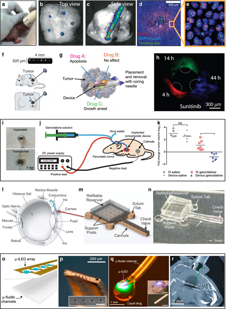
Fig. 9. Microfluidic in vivo drug delivery.
a–e The CIVO device developed with PresageBio. a The CIVO device, which consists of an array of hypodermic needles, being used for injection to a mouse tumor. b Top-view of a tumor site after injection of microliter-quantities of the drug; the green label is injection tracking dye added to the drug solutions. c IVIS imaging of the intact tumor showing the column-like distribution of the tracking dye signal from a single needle spanning the z-axis of the tumor. d The blue label is nuclei labeled with DAPI; the green label is an injection tracking dye; the orange label is a drug-specific biomarker. e The resulting images were processed by a custom image analysis platform, which classifies the cells within each region of interest as biomarker-positive (green dots) or biomarker-negative (red dots). Adapted with permission from ref. 71. f–h An implantable microdevice to perform multiplexed in vivo drug sensitivity testing in tumors. f A device with multiple (up to 16) reservoirs that can be implanted into a tumor using a coring needle. g Each reservoir is loaded with microdoses of anti-cancer agents, which are diffusively released upon implantation. h Release of a microdose of sunitinib (50% in PEG-1450) into BT474 tumors at three time points. Adapted with permission from ref. 70. i–k Local iontophoretic administration of cytotoxic therapies to solid tumors. i Photographs of the microfluidic iontophoretic devices used to administer drugs by internally after implantation (top) or transdermally (bottom). j Experimental setup for delivery of gemcitabine to pancreatic tumors. k Graph depicting the fold change in tumor volume as a measure of the efficacy after treatment of pancreatic cancer PDX mice with gemcitabine, I.V. gemcitabine, device saline, or I.V. saline twice per week for 7 weeks. ***p < 0.0001. Adapted with permission from ref. 207. l–n Treatment of ocular diseases with a refillable microfabricated drug delivery device implanted under the conjunctiva. l Illustration of device placement on the temporal side of the eye, providing easier access for a refill and improving patient comfort. m 3D schematic of the device. n Photograph of the device. Adapted with permission from ref. 208. o–r A wireless optofluidic system for programmable in vivo pharmacology and optogenetics. o Schematic diagram of the integration of a soft microfluidic probe with a flexible array of µ-ILEDs (inorganic LEDs, each with lateral dimensions of 100 µm × 100 µm and thicknesses of 6.54 µm) and metal interconnect traces on a 6-µm-thick film of PET. p The tip end of an optofluidic probe. (Inset) SEM of the outlets of the microfluidic channels. q Optofluidic neural probe during simultaneous drug delivery and photostimulation. (Insets) Comparison of this device (top) with a conventional metal cannula. r Computed tomographic x-ray images of the mouse model with an optofluidic neural probe (colorized green) implanted into the brain. Adapted with permission from ref. 214

