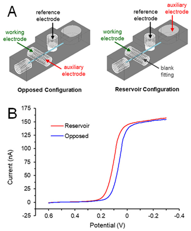
Figure 3.
Effects of electrode orientation on voltammogram. (A) Diagrams of the electrode placements. The auxiliary electrode was placed either opposite the working electrode (blue trace in B) or downstream in the reservoir (red trace in B). (B) Linear sweep voltammograms of 10 mM ferricyanide (in 0.5 M KCl) under flowing conditions (pumping solution at 15 μL/min).

