
Fig. 9.
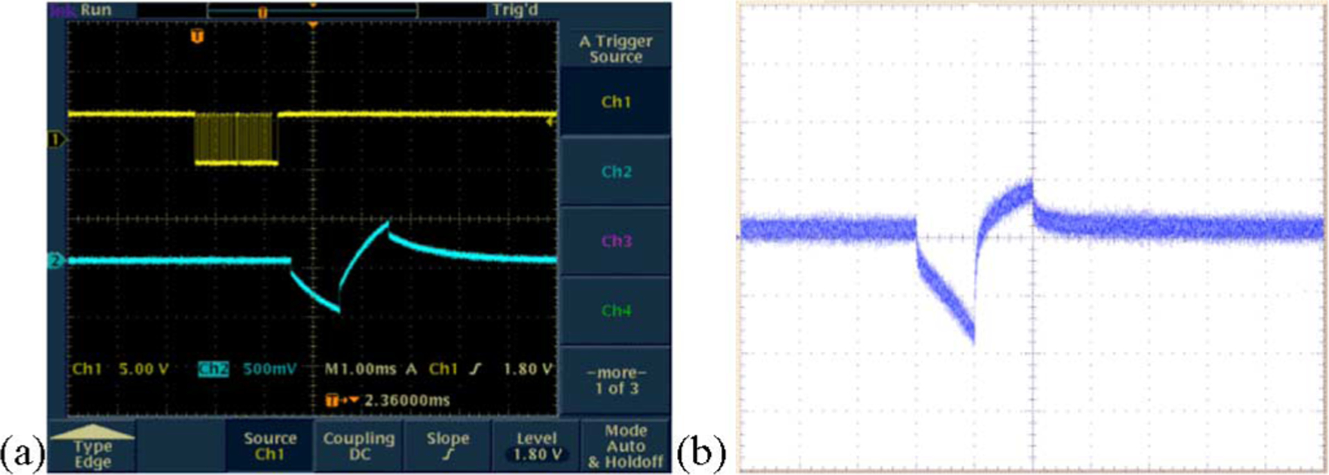
Typical electrode voltage waveforms (a) when the stimulator drove a dummy load consisting of a series resistor of 4 kΩ (representing the access resistance and the series resistance of the lead), and a parallel combination of a 20 kΩ resistor and a 0.047 μF capacitor representing the electrode–tissue interface (the top trace shows the binary bitstream used to command the device and the bottom trace shows the voltage output.) (b) Representative electrode voltage waveform when the stimulator was wirelessly powered in saline solution, measured using a “test tail” extension of the IrOx electrode array that reached back out of the bath. The noise is due to RF interference from the transmitter.