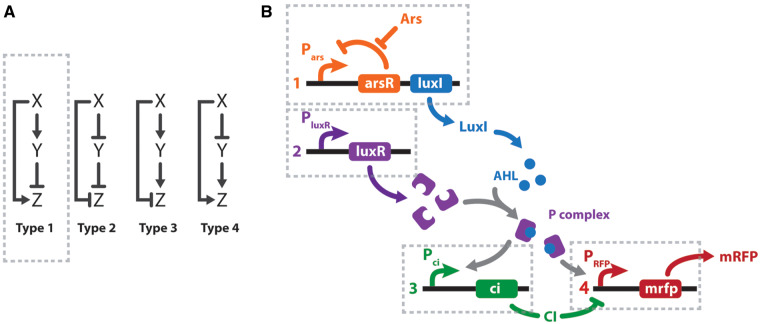
Figure 1.
I-FFL schemes. (A) Canonical I-FFL circuits. Composing elements: input (X), auxiliary regulator (Y), and output (Z). (B) Design of a genetic type 1 I-FFL or I1-FFL circuit from BioBricks. Transcription units are numbered 1–4 under the regulation of Pars, PluxR, Pci and Phyb promoters, respectively. Arsenic (Ars) and mRFP are the input and output signals of the system. To exploit the modular design, the sensor (transcription unit 1) and effector (transcription units 2–4) modules could be located in two different bacteria. Activation is represented by normal arrows and repression by barred arrows.

