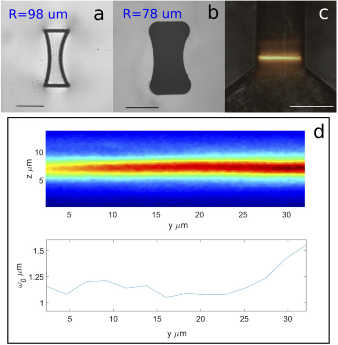
Fig. 4.
Example of spheric cylindrical microlens with curvature radius of right hand surface. Microscope images before (a) and after etching (b). The radius of each lens is reported. It can be seen that the precompensation of the irradiated geometry leads to the correct final dimension; (c) Image of the rhodamine signal, inside the inlet microchannel, when irradiated by the light-sheet. Superposition of fluorescence and bright-field channels; All scalebars correspond to . (d) Acquired image of light-sheet fluorescence profile and corresponding waist fit (). The plot shows the fit of the light sheet waist taking into consideration the acquisition objective depth of field. Each point is averaged on 10 raw data points. This plot corresponds to half of the light-sheet thickness.

