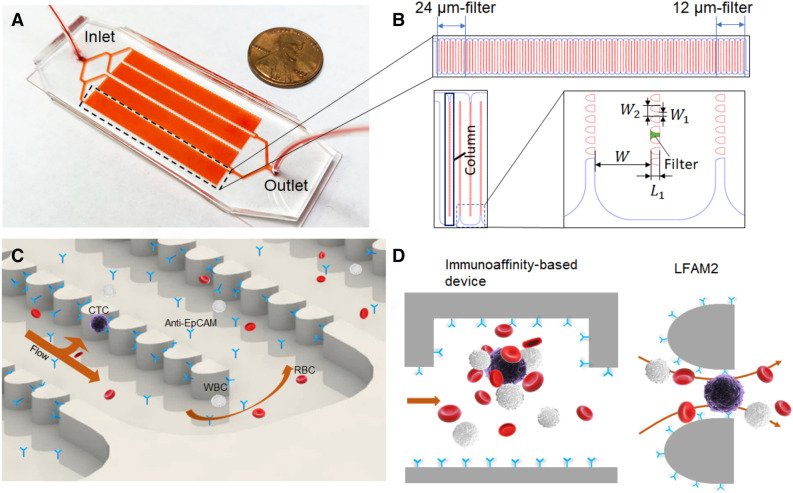
Figure 1.
(A) Photo of the LFAM2 device, showing its size relative to a penny. (B) One serpentine main channel shown at the top, consisting of the 24-µm filter zone near the inlet and the 12-µm filter zone near the outlet. On the lower left are a “column” of filters and the “channel elbow,” which is further zoomed in on the lower right, showing the dimension marks of the serpentine main channel and filters. The device design was drawn by using AutoCAD 2016. (C) Illustration of a two-dimensional flow in the device, represented by one arrow along the main channel and one arrow towards lateral filters. This parking-lot-like arrangement prevents cells from clogging. Antibodies are immobilized on the surfaces of filters and channels for CTC capture. The drawing was created by using SolidWorks 2017. (D) Cartoons comparing a conventional immunoassay-based CTC device with LFAM2. Left: a herringbone-mixer-based CTC device using immunoaffinity capture where a CTC is cloaked by a number of blood cells. Right: a microfilter forces the direct interactions between antibodies on the filter surface and biomarkers on a CTC, while reducing the interference of other blood cells. The cartoons were drawn by using Microsoft PowerPoint.

