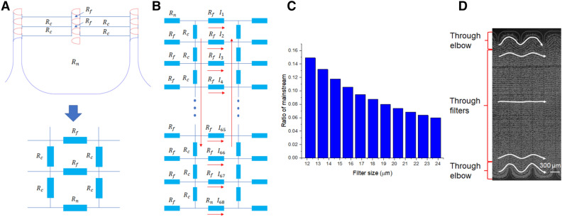
Figure 2.
(A) Serpentine channel and lateral filters are modeled as a network of hydrodynamic resistors. The filters () in each column are modeled as a group of hydrodynamic resistors in parallel. The serpentine main channel is modeled as a series of hydrodynamic resistors (), as well as the channel elbows (). (B) The three basic components (Rf, Rc, and Rn) are interconnected in a hydrodynamic resistor network. Their designations from 1 to 68 in the adjacent column are in a reverse order, just like the flow directions indicated by the red arrows. (C) The mainstream ratio calculated for all filter sizes in the LFAM2 device. (D) The flow pattern observed in the LFAM2 device when a blood sample is pumped through the device. The filter size in the picture is 18 µm and the scale bar is 300 µm. Five representative streaklines are added for easy visualization of the cell trajectory paths.

