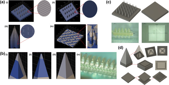
Fig. 1.
Optimisation of different 3D printing parameters (Describe software settings): (a) (i) distance between layers (“slicing”); (ii) shell parameters (distance between hatching lines within a layer – “hatching distance”, shell contour count, and number of filled slices at the bottom of the shell – “base slice count”); (iii) scaffold parameters (spacing between scaffold walls and floors, thickness of scaffold walls and scaffold floor); and (iv) “splitting” mode (block width in X and Y direction, block height and block offset in X, Y and Z direction); (b) effect of block size and position in printing the needle tip with (i) two blocks, (ii) one short block in Z direction, and (iii) one single and large block [(iv), printed example]; (c) Two-step 3D printing of long MN master templates (1.3 mm high needles) and additional baseplate; (d) cavities introduced in the MN, pedestal and baseplate designs.

