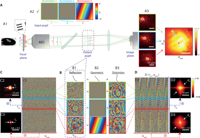
Fig. 1. Principle of the distortion matrix approach.
(A) A resolution target (USAF 1951) is positioned underneath an 800-μm-thick sample of rat intestine (A1). In scanning microscopy, raster scanning in the focal plane is obtained using a set of plane-wave illuminations in the input pupil (A2). In the presence of sample-induced aberrations, the detected intensity will exhibit a much larger extent compared to the ideal PSF (A3). The resulting full-field image displays a low contrast and a reduced resolution (A4). (B) In the output pupil plane, the phase of the reflected wave field (B1) can be split into a diffraction (B2) and a distortion (B3) term. (C and D) The reflected distorted wave fields can be stored along column vectors to form the reflection and distortion matrices, R and D, respectively. The phase of R and D is displayed in (C1) and (D1), respectively. The autocorrelations of the complex reflected/distorted wave fields are computed in the focal (C2/D2; see section S2) and in the pupil (C3/D3; see section S1) planes, both in dB. All the data shown here are extracted from the rat intestine imaging experiment. Photo credit: Amaury Badon, CNRS. NA, numerical aperture.

