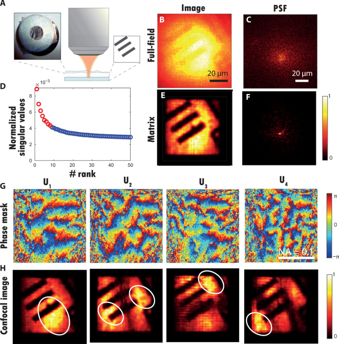
Fig. 4. Matrix imaging over multiple IPs.

(A) Schematic of the experiment. A resolution target (USAF 1951) is positioned at a distance d = 1 mm underneath a rough plastic film (see inset). (B) Original full-field image ℱ0 (Eq. 14). (C) Example of PSF deduced from a column of the raw focused matrix R0. (D) Plot of the normalized singular values of D. The red circles correspond to the eight first singular values (signal subspace), while the noisy singular values are displayed in blue. (E) Matrix image constructed from the eight first eigenstates of D (Eq. 20). (F) Example of PSF deduced from a column of the corrected focused matrix R1. (G) Phase of the four first singular vectors Up. (H) Confocal images deduced from the focused reflection matrices Rp (Eq. 18). Photo credit: Amaury Badon, CNRS.
